Manufacture of light emitting devices with phosphor wavelength conversion

Inactive Publication Date: 2010-11-25
INTEMATIX
View PDF25 Cites 48 Cited by
  • Summary
  • Abstract
  • Description
  • Claims
  • Application Information

AI Technical Summary

Benefits of technology

[0029]The present invention arose in an endeavor to address, at least in part, the problem of color hue and / or CCT variation of light emitting devices that include phosphor wavelength conversion and to reduce or even eliminate the need for binning packaged devices.
[0035]Alternatively the stamp can be a multiple-use item and can comprise for example a metal such as stainless steel, a polymer material such as a polycarbonate, an acrylic, a silicone or an epoxy or a glass. Preferably the stamp further comprises a coating of, or is fabricated from, a non-stick material such as PTFE (polytetrafluoroethylene) for example Teflon® (“Teflon” is a registered trademark of Du Pont) to aid in the removal of the stamp. Moreover, the stamp can be resiliently deformable to assist in its removal and a release agent can be used to further aid in removal of the stamp.

Problems solved by technology

A drawback with such a method of manufacture is cost, since phosphor has to be applied to the LED chip on an individual basis.
The problem of color / CCT variation is compounded by the fact that the human eye is extremely sensitive to subtle changes in color hue especially in the white color range.
Furthermore, in applications in which the device includes further optical components, in particular a lens, to focus the output light, such color / CCT variation can become a significant problem.
In addition to the problem of non-uniformity in emitted color / CCT due to the variation in path length through the phosphor / polymer encapsulation, it is found that the phosphor material(s) can accumulate unevenly during curing of the liquid polymer resulting in a non-uniform distribution of the phosphor material(s) over the LED chip and in particular on the edges of the LED chip, which will also emit light, where there may be little or no phosphor material(s).
To overcome this problem a greater quantity of phosphor material is often used though this will result in a corresponding decrease in emitted light intensity.
A disadvantage of binning is increased production costs and a low yield rate as often only two out of the nine bins are acceptable for an intended application resulting in supply chain challenges for white LED suppliers and customers.
Although such a process can produce LEDs with a more consistent CCT both the LED dies and phosphor sheet need to be binned and this can make the process expensive.
Although this process can produce LEDs with a desired CCT, binning of LEDs and phosphor caps is required and this can make the process time consuming and expensive.

Method used


Image

  • Manufacture of light emitting devices with phosphor wavelength conversion
  • Manufacture of light emitting devices with phosphor wavelength conversion
  • Manufacture of light emitting devices with phosphor wavelength conversion

Examples


Embodiment Construction

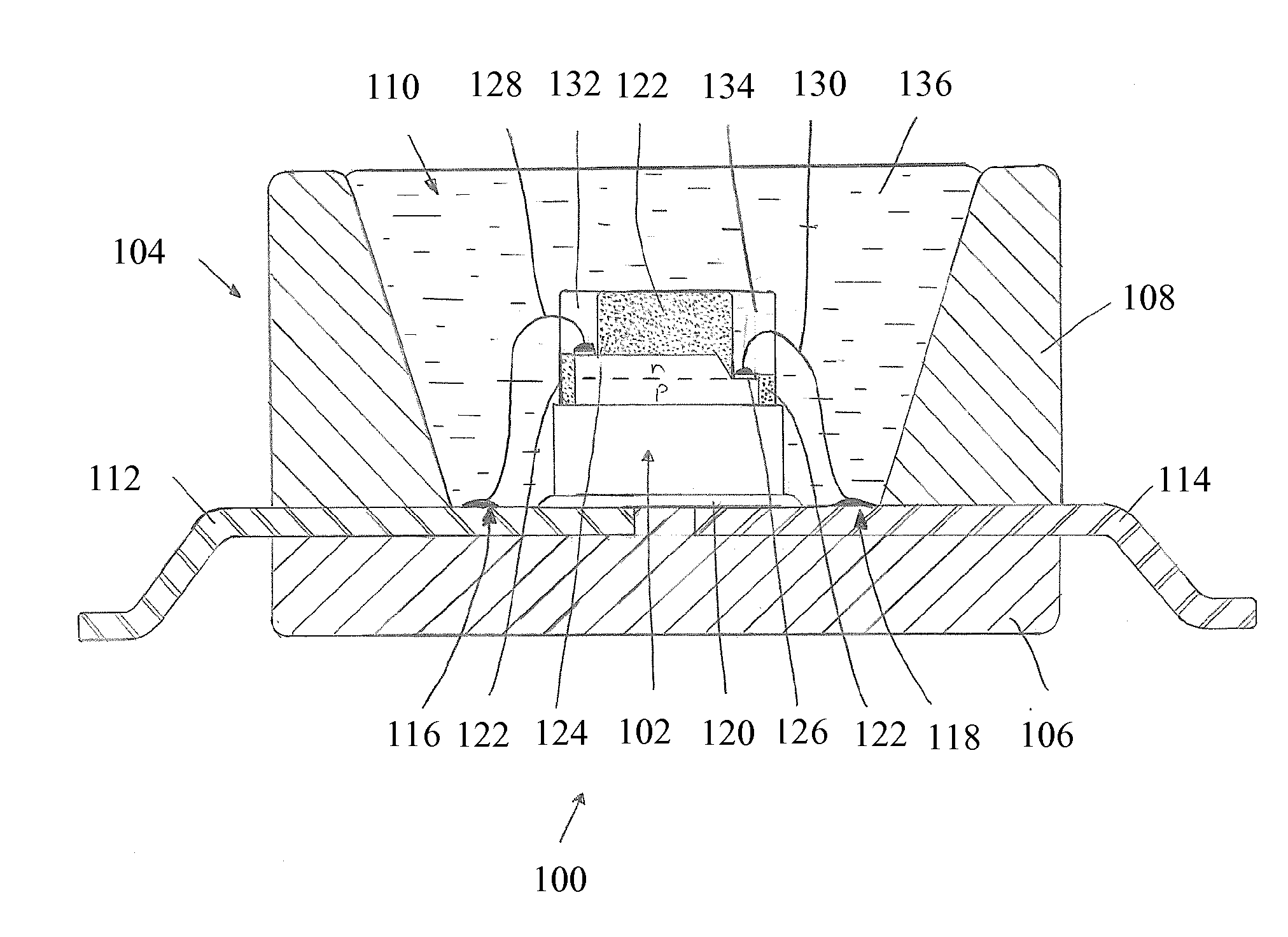
[0049]Embodiments of the invention concern methods of manufacturing a light emitting device with phosphor wavelength conversion and in particular methods of applying / processing the phosphor material on an LED wafer prior to division of the wafer into individual LED chips. More particularly the method concerns patterning of the phosphor material to enable electrical connections to be made to the LED chip's electrode contacts once the wafer is subsequently divided into individual LED chips. The term “LED wafer” refers to a wafer (substrate) on which the LED chips are fabricated by depositing layers of n-type and p-type semiconductor materials. This is to be contrasted with a wafer (substrate) onto which individual LED chips are mounted post fabrication.

[0050]In this specification like reference numerals are used to denote like parts. FIG. 3 is a schematic sectional view of a white light emitting device 100 with phosphor wavelength conversion in accordance with the invention. The devic...


PUM


Abstract

A method of manufacturing a light emitting device comprises: a) depositing over substantially the entire surface of a LED diode wafer having an array of LEDs formed on a surface thereof a mixture of at least one phosphor material and a polymer material, wherein the polymer material is transmissive to light generated by the LEDs and to light generated by the at least one phosphor material; b) mechanically stamping the phosphor / polymer mixture with a stamp having features configured such as to form passages in the phosphor / polymer corresponding to electrode contact pads of each LED thereby enabling access to each electrode contact pad; c) curing the polymer; d) removing the stamp; and e) dividing the LED wafer into individual light emitting devices. The stamp comprises a dissolvable material (polyvinyl alcohol) and the stamp is removed by dissolving it using a solvent (e.g. water).

Description

CROSS-REFERENCE TO RELATED APPLICATIONS[0001]This application claims the benefit of priority of U.S. Provisional Application No. 61 / 179,668, filed May 19, 2009, the contents of which are incorporated herein by reference.BACKGROUND OF THE INVENTION[0002]1. Field of the Invention[0003]The invention relates to methods of manufacture of light emitting devices with phosphor wavelength conversion. More particularly the invention concerns a method of applying a phosphor material to a light emitting diode (LED).[0004]2. Description of the Related Art[0005]White light emitting LEDs (“white LEDs”) are known in the art and are a relatively recent innovation. It was not until LEDs emitting in the blue / ultraviolet part of the electromagnetic spectrum were developed that it became practical to develop white light sources based on LEDs. As taught, for example in U.S. Pat. No. 5,998,925, white LEDs include one or more phosphor materials, that is photo-luminescent materials, which absorb a portion o...

Claims


Application Information

Patent Timeline
IPC IPC(8): H01L33/50H01L21/50
CPCH01L33/0095H01L33/50H01L33/54H01L2933/0041H01L2224/48091H01L2224/73265H01L2224/49107H01L2224/48247H01L2224/32245H01L2224/8592H01L2924/00014H01L2924/00012H01L24/73H01L2924/181
Inventor CHEN, GENGMELMAN, JONATHAN
Owner INTEMATIX
Why Eureka
Try Eureka