Peripheral interface device for color recognition

a color recognition and interface technology, applied in the direction of optical radiation measurement, instruments, spectrometry/spectrophotometry/monochromators, etc., can solve the problems of complex implementation of pattern hardware and pattern reading hardware, lack of object identification of electrostatic and capacitive positioning, and lack of object identification of pattern itself. , to achieve the effect of reducing hardware size and cos

Inactive Publication Date: 2010-12-07
LEAPFROG ENTERPRISES
View PDF15 Cites 16 Cited by
  • Summary
  • Abstract
  • Description
  • Claims
  • Application Information

AI Technical Summary

Benefits of technology

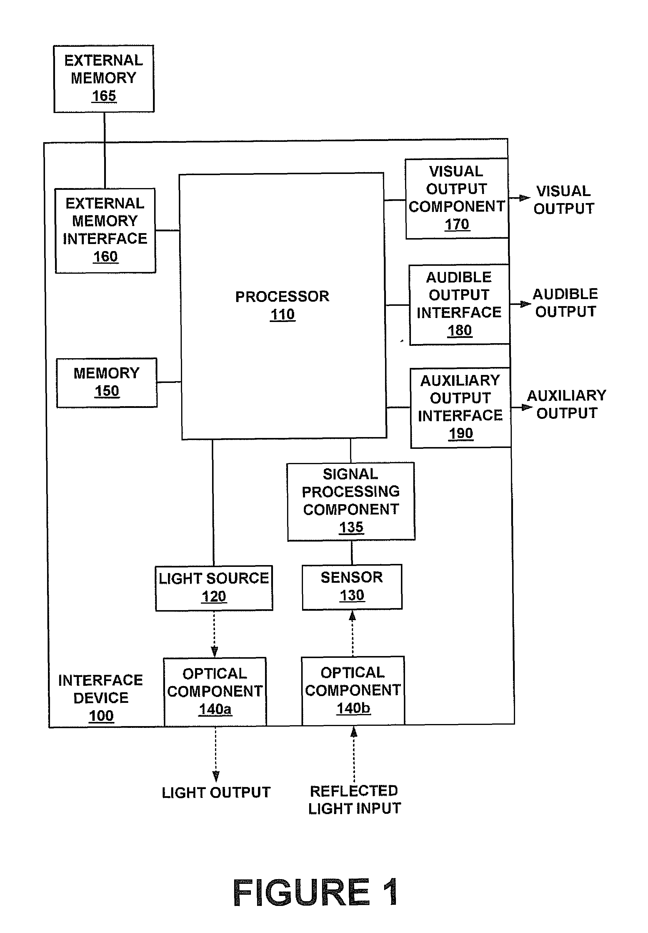
[0004]Accordingly, a need exists for a peripheral interface device capable of both position determination and object identification. Further, a need exists for a peripheral interface device that is able to determine position and identify objects with reduced hardware size and cost. Embodiments of the present invention provide novel solutions to these needs and others as described below.

Problems solved by technology

While the coded dot patterns may allow an input device to recognize a dot coding and identify its position on the pattern, the pattern itself provides no means for object identification.
Additionally, both the pattern itself and the hardware for reading the pattern are complex and expensive to implement considering the cost of the optical sensors for reading the pattern, the cost of printing a usable pattern, etc.
Similar to the coded dot patterns discussed above, electrostatic and capacitive positioning also lack means for object identification.
Additionally, both technologies are expensive to implement and discourage use in small products given the large size of the required hardware.

Method used


Image

  • Peripheral interface device for color recognition
  • Peripheral interface device for color recognition
  • Peripheral interface device for color recognition

Examples


Embodiment Construction

[0027]Reference will now be made in detail to embodiments of the present invention, examples of which are illustrated in the accompanying drawings. While the present invention will be discussed in conjunction with the following embodiments, it will be understood that they are not intended to limit the present invention to these embodiments alone. On the contrary, the present invention is intended to cover alternatives, modifications, and equivalents which may be included with the spirit and scope of the present invention as defined by the appended claims. Furthermore, in the following detailed description of the present invention, numerous specific details are set forth in order to provide a thorough understanding of the present invention. However, embodiments of the present invention may be practiced without these specific details. In other instances, well-known methods, procedures, components, and circuits have not been described in detail so as not to unnecessarily obscure aspect...


PUM

PropertyMeasurementUnit
coloraaaaaaaaaa
color measurementaaaaaaaaaa
color codingaaaaaaaaaa

Abstract

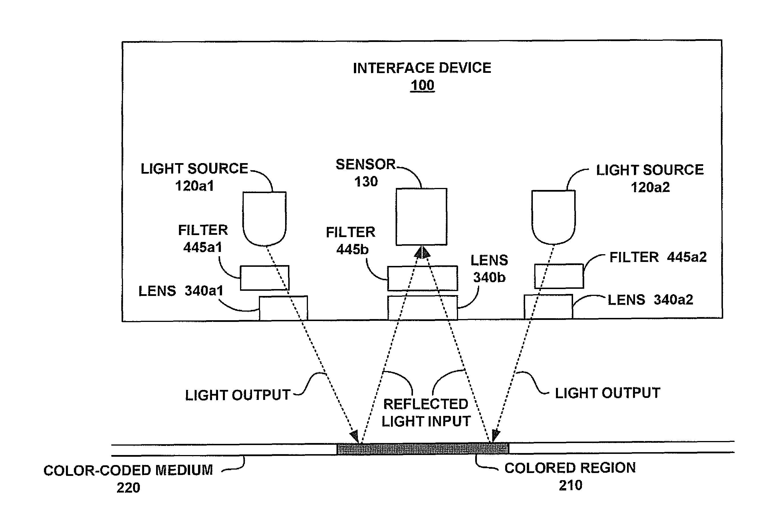
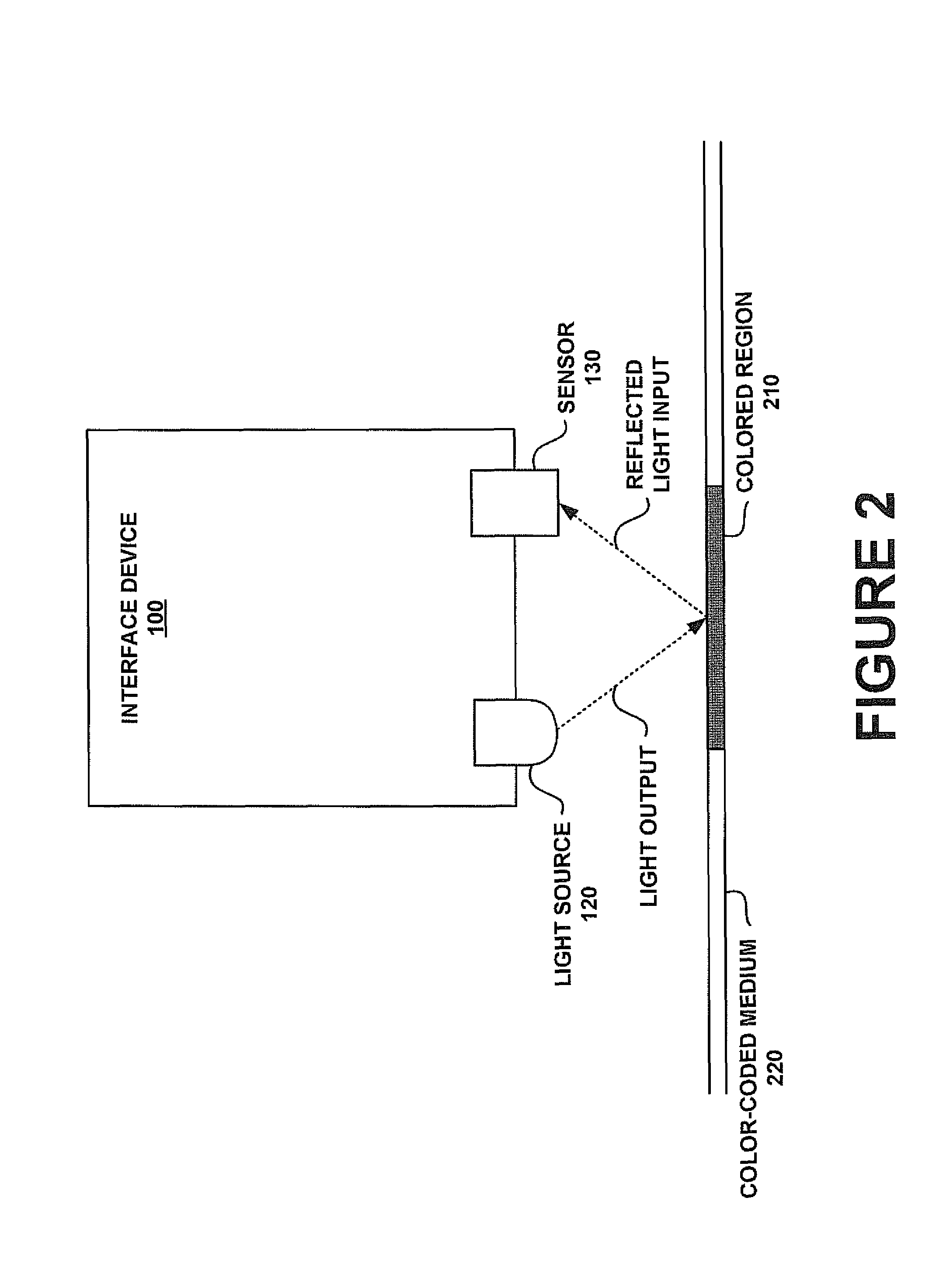
A peripheral interface device for determining the color of a surface, where the surface color may then be used to determine device position and identify objects. Embodiments provide a device capable of directing different colors of light (e.g., red, green and blue) onto a surface and measuring relative intensities of the reflected colors to determine the color of the surface. The reflection and measurement of each color may be performed separately. Alternatively, composite-colored light may be directed at the surface, which may then be filtered to extract the different colors and enable measurement of their relative intensities. As such, the device can detect regions of a given color and regions of different shades of the same color, which may then be used to determine the position of the device and/or identify an object.

Description

BACKGROUND OF THE INVENTION[0001]Many hardware systems running software applications require some type of user input. While input peripherals once consisted primarily of joysticks and mice, modern systems require more advanced user inputs. For example, educational tools and other software applications invite users to interact with objects separate from the components of the system itself (e.g., a display screen coupled to the system, etc.), thereby necessitating additional inputs from peripherals designed to interact with the separate objects. Since numerous objects can be used with the system and the objects can be moved independently of the system, position determination and object identification have become important inputs to modern systems.[0002]One conventional solution to position determination is the use of a coded dot pattern such as the products offered by the Anoto Group AB of Sweden. While the coded dot patterns may allow an input device to recognize a dot coding and ide...

Claims


Application Information

Patent Timeline
Patent Type & Authority Patents(United States)
IPC IPC(8): G01N21/25
CPCG01J3/02G01J3/0208G01J3/50G01J3/501G01J3/51G06F3/03542G01J3/513
Inventor MILFORD, PETERLYNCH, LARRYFREEMAN, RICHARD
Owner LEAPFROG ENTERPRISES
Why Eureka
Try Eureka