
Rake receiver and de-spreading method thereof

a receiver and channel estimation technology, applied in the field of rake receivers, can solve the problems of user interference, mutual interference of signals between users, damage to the orthogonality between spreading codes, etc., and achieve the effect of reducing the bit error rate of signals and effectively reducing the complexity of receiving terminals

Active Publication Date: 2010-12-07
MEDIATEK INC
View PDF7 Cites 3 Cited by
  • Summary
  • Abstract
  • Description
  • Claims
  • Application Information

AI Technical Summary

Benefits of technology

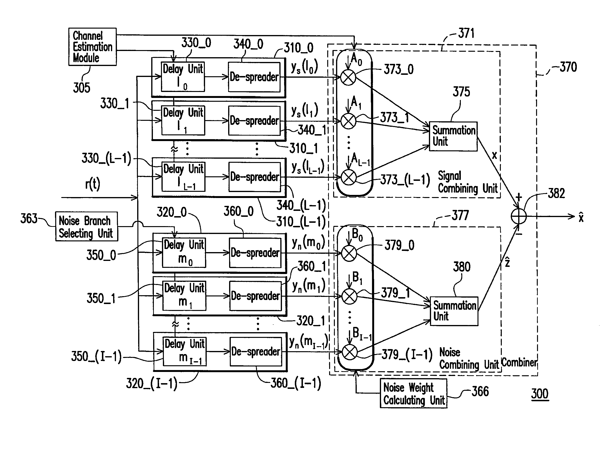
[0020]Accordingly, the present invention is directed to a rake receiver for reducing the bit error rate of a signal demodulated by a receiving terminal, and meanwhile effectively reducing a complexity of the receiving terminal.
[0021]The present invention is also directed to a data demodulation method for estimating and eliminating noises and interference in the received signal under a condition of low complexity.
[0032]The present invention uses an interference-plus-noise estimation value generated by the plurality of noise branches and the noise combining unit to eliminate the noises in the main signal, so as to lower the bit error rate. In addition, in the present invention, when the noise weight is calculated, it is only necessary to calculate the inverse matrix of the sub-matrix Rn in the noise matrix Ru, and thereby reducing the operations at the receiving terminal.

Problems solved by technology

Therefore, when the signal is interfered by the multi-path in the channel, the orthogonality between the spreading codes is also damaged, as a result, the signals between the users are mutually interfered, that is, multiple-user interference (MUI).
In addition, the interference of the multi-path also causes inter-symbol interference (ISI) for the same user.
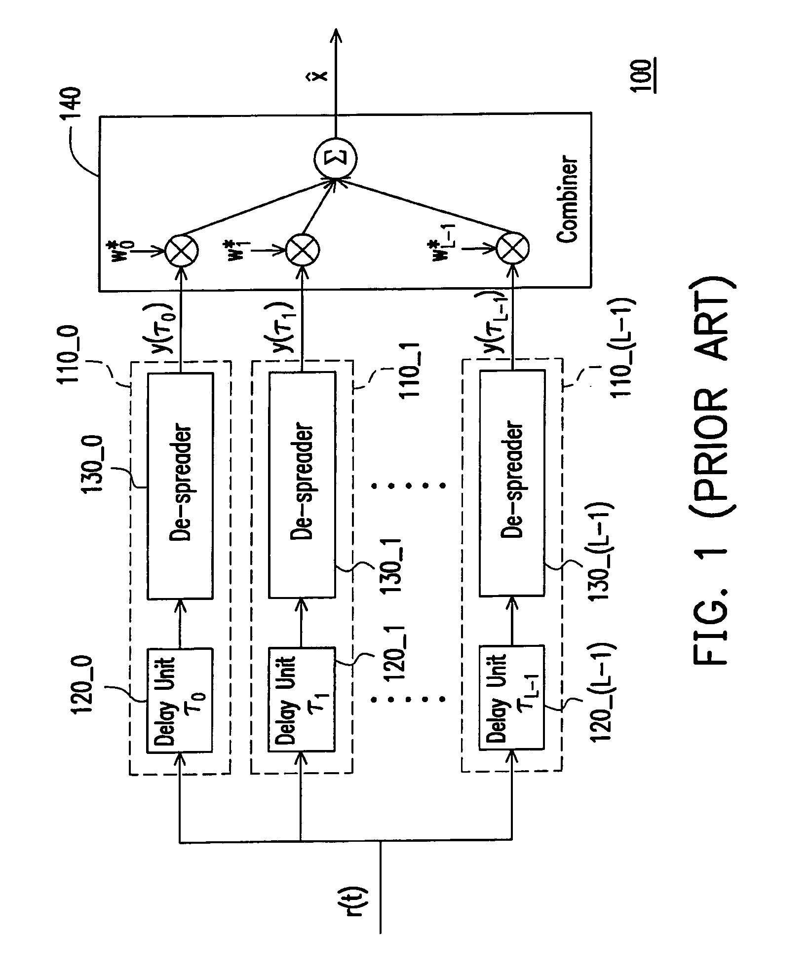
However, the conventional rake receiver only considers the attenuation of the signals caused by the multi-path channel, but cannot overcome the MUI and the ISI problems.
Therefore, the conventional rake receiver ignores the MUI and the ISI, such that the performance of the receiving terminal becomes relatively poor, and meanwhile the bit error rate of the signals demodulated by the receiving terminal becomes relatively large.
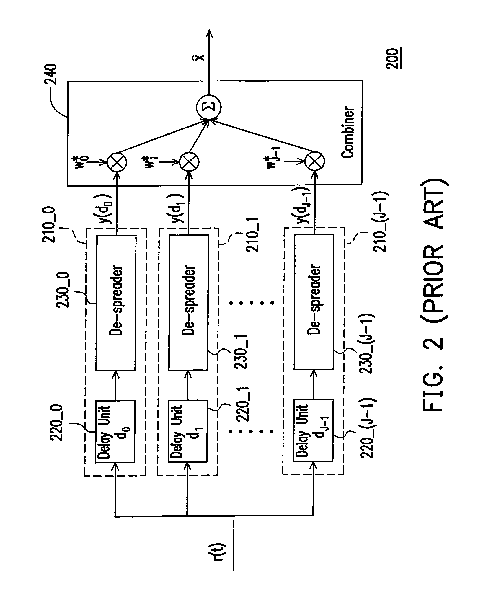
In addition, the time d0-dJ-1 designed through maximizing SNR also requires a considerably amount of calculations.

Method used


Image

  • Rake receiver and de-spreading method thereof
  • Rake receiver and de-spreading method thereof
  • Rake receiver and de-spreading method thereof

Examples


Embodiment Construction

[0042]In order to overcome attenuation of the multi-path channel transmission and to restrain colored Gaussian noises in the channel, recently a G-RAKE receiver is proposed to improve the performance of the receiving terminal and the bit error rate. However, the operation complexity of the receiving terminal is greatly enhanced, and a large number of calculations are required. Therefore, the rake receiver provided by the present invention can maintain the performance and bit error rate as equivalent to the G-RAKE receiver, and can effectively lower the complexity and reduce the calculations in the operation.

[0043]In order to clearly illustrate the implementing manner of the present invention, it is assumed that the rake receiver provided by the present invention is applied to a spread-spectrum system. That is to say, a transmitting terminal makes the signal to be transmitted be multiplied by a spreading sequence. The spreading system can be a direct sequence code division multiple a...


PUM


Abstract

The invention relates to a rake receiver and a method for de-spreading thereof. A plurality of noise branches is adopted for producing a plurality of noise components in the rake receiver. Next, a noise combining unit adjusts each noise component according to a plurality of noise weights, so as to combine the noise components to obtain an interference-plus-noise estimation value. The rake receiver eliminates the noises in the main signal generated by the signal branches through using the interference-plus-noise estimation value. Therefore, the performance of a receiving terminal can be enhanced.

Description

CROSS-REFERENCE TO RELATED APPLICATION[0001]This application claims the priority benefit of Taiwan application serial no. 96123507, filed on Jun. 28, 2007. The entirety of the above-mentioned patent application is hereby incorporated by reference herein and made a part of this specification.BACKGROUND OF THE INVENTION[0002]1. Field of the Invention[0003]The present invention relates to a rake receiver. More particularly, the present invention relates to a rake receiver using channel estimation.[0004]2. Description of Related Art[0005]Wireless communication system uses radio waves to transmit messages. During the process of transmitting electric waves, the electric waves are affected by buildings or automobiles in the environment, so signals from a transmitting terminal finally reach a receiving terminal after passing through various different reflection or refraction paths, and the time for the signal reaches the receiving terminal varies depending upon a different path. Therefore, ...

Claims


Application Information

Patent Timeline
Patent Type & Authority Patents(United States)
IPC IPC(8): H04B1/707
CPCH04B1/7103H04B1/712H04B2201/709727H04L25/03006
Inventor BAI, CHENG-ZONGLI, HSUEH-JYHCHEN, PO-YING
Owner MEDIATEK INC
Learn More