Voice coil assembly, loudspeaker using the same, and method for producing the same

a voice coil and loudspeaker technology, applied in the field of flat thin loudspeakers, can solve the problems of increasing the total weight of the loudspeaker diaphragm, the loudspeaker is likely to have insufficient rigidity to vibrate as an integral unit without divided vibration, and the overall height of the loudspeaker, etc., to achieve flat frequency response, reduce divided vibrations, and increase the rigidity of the bobbin

Inactive Publication Date: 2010-12-07
ONKYO KK
View PDF11 Cites 6 Cited by
  • Summary
  • Abstract
  • Description
  • Claims
  • Application Information

AI Technical Summary

Benefits of technology

[0033]As a result, it is possible to realize a flat thin loudspeaker having reduced divided vibrations and a flat frequency response. In the voice coil assembly of the present invention, each internal rectangular coil is fixed to the inner wall surface defining a rectangular space of the bobbin, and adjacent bobbins of the voice coil assembly, i.e., adjacent internal-winding voice coils, are adhered and fixed together. As a result, it is possible to increase the bobbin rigidity, reduce divided vibrations of the bobbins, and suppress operation defects such as the occurrence of an abnormal noise due to adjacent bobbins contacting each other. Since the amount of adhesive used to connect adjacent bobbins to each other can be reduced, it is possible to reduce the weight of the loudspeaker vibrating member, and to improve the reproduction efficiency of the loudspeaker, thereby realizing a stable sound reproduction.
[0034]Also when the voice coil assembly uses a lattice-shaped bobbin, it is similarly possible to increase the bobbin rigidity and to suppress divided vibrations of the bobbins. In the lattice-shaped bobbin, two internal rectangular coils fixed in two rectangular spaces with a partition wall therebetween are arranged so that a direction of an audio signal current flow along one side x1 of one internal rectangular coil v1 that is neighboring the partition wall is the same as that along one side x2 of the other internal rectangular coil v2 that is neighboring the partition wall. The thickness tb1 of the partition wall of the lattice-shaped bobbin is smaller than the thickness tb2 of other portions of the inner wall surface. Moreover, the thickness tb1 of the partition wall is less than or equal to the total thickness tc0, being the sum of the thickness tc1 of one side x1 of one internal rectangular coil v1 and the thickness tc2 of one side x2 of the other internal rectangular coil v2. As a result, the thickness tb1 of the partition wall of the lattice-shaped bobbin can be made smaller than the thickness tb2 of other portions of the inner wall surface to thereby reduce the total weight of the voice coil assembly including the lattice-shaped bobbin. The effect of reducing the total weight by reducing the thickness of each partition wall becomes more significant when the number of rectangular spaces of the lattice-shaped bobbin is increased, thereby also increasing the number of partition walls.
[0035]If the magnetic gap of the magnetic circuit can be further narrowed, the magnetic flux density is improved, thereby desirably improving the efficiency of the loudspeaker. Thus, in the voice coil assembly of the present invention, the sides x1 and x2 of the two internal rectangular coils v1 and v2 along the partition wall are fixed together by an adhesive with the partition wall being not interposed therebetween, and upper end surfaces of the sides x1 and x2 are fixed to a lower end surface of the partition wall by an adhesive. Alternatively, in the voice coil assembly of the present invention, the partition wall of the lattice-shaped bobbin further includes a partition wall extension being interposed between the sides x1 and x2 of the two internal rectangular coils v1 and v2 along the partition wall, and the thickness tb0 of the partition wall extension is less than or equal to the thickness tb1. Thus, the partition wall of the lattice-shaped bobbin between the sides x1 and x2 of the internal rectangular coils v1 and v2 along the partition wall is omitted or is replaced by a partition wall extension thinner than the partition wall, whereby it is possible to further reduce the weight of the lattice-shaped bobbin, and a loudspeaker with reduced gap defects and a high efficiency can be realized even if the magnetic gap is further narrowed.
[0037]As a result, it is possible to realize a flat thin loudspeaker having reduced divided vibrations and a flat frequency response. In the voice coil assembly of the present invention, each internal rectangular coil is fixed to the inner wall surface of the bobbin defining a rectangular space, and two internal-winding voice coils along the partition wall can be adhered and fixed to each other. As a result, it is possible to increase the bobbin rigidity and reduce the weight of the loudspeaker vibrating member, whereby it is possible to improve the reproduction efficiency of the loudspeaker, thereby realizing a stable sound reproduction.
[0038]In addition, the magnetic circuit has open holes defined by the yoke at opposite ends thereof, and the outer wall surfaces at the opposite ends of the voice coil assembly are exposed through the open holes. Where the frame has frame holes which are communicated to the open holes of the magnetic circuit, the outer wall surfaces at the opposite ends of the voice coil assembly are exposed through the open holes of the magnetic circuit and the frame holes. Thus, with a voice coil assembly of a loudspeaker of the present invention, the internal rectangular coils are fixed to the inner wall surfaces defining the rectangular spaces of the bobbin, and no coil exists on the outer wall surfaces of the voice coil assembly. During the production of a loudspeaker, an assembly jig for appropriately positioning the voice coil assembly in the magnetic gap of the magnetic circuit can be held against the outer wall surface of the voice coil assembly for holding the voice coil assembly. As a result, it is possible to realize a loudspeaker with reduced operation defects such as the occurrence of an abnormal noise due to the voice coil assembly contacting the magnetic circuit. Where the assembly jig includes two straight holding sections, an end surface holding section, and a connecting section therebetween, the step of providing a loudspeaker vibrating system can be carried out by allowing an adhesive to cure with the assembly jig being fit in place, and the assembly jig can be removed after the adhesive cures to thereby provide a loudspeaker vibrating system that can vibrate.

Problems solved by technology

With a flat diaphragm, as compared with a cone diaphragm, the overall height of the loudspeaker will be small, but the loudspeaker is likely to have insufficient rigidity for vibrating as an integral unit without divided vibrations.
However, as seen in FIG. 2 of this publication, each voice coil of the conventional voice coil cluster is wound around the outside of a frame (equivalent to a bobbin), and adjacent ones of the bobbins forming the voice coil cluster cannot be attached closely together, and will rather be spaced apart from each other by the thickness of the wire diameter of the voice coils, even when adjacent voice coils are jointed together.
If the bobbin rigidity is insufficient, bobbins may vibrate to cause divided vibrations, and adjacent bobbins may contact each other to produce an abnormal noise.
This increases the total weight of the loudspeaker diaphragm, thereby reducing the reproduction efficiency of the loudspeaker.

Method used


Image

  • Voice coil assembly, loudspeaker using the same, and method for producing the same
  • Voice coil assembly, loudspeaker using the same, and method for producing the same
  • Voice coil assembly, loudspeaker using the same, and method for producing the same

Examples


embodiment 1

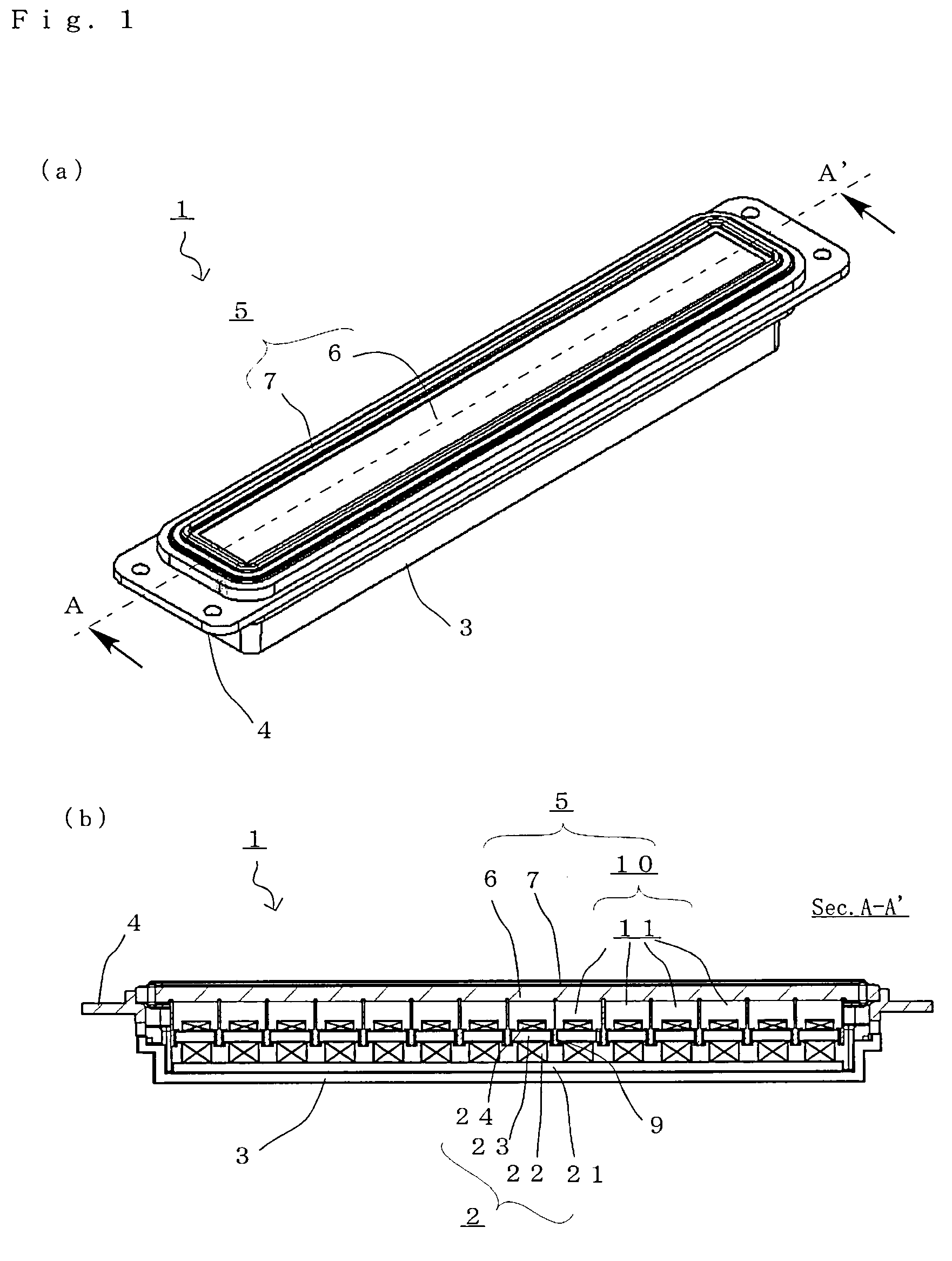
[0053]FIGS. 1A and 1B are views illustrating a flat thin loudspeaker 1 according to a preferred embodiment of the present invention. FIG. 1A is a perspective view illustrating the loudspeaker 1 with a flat diaphragm 6 facing up, and FIG. 1B is a cross-sectional view taken along line A-A′ illustrating an internal structure of the flat thin loudspeaker 1. These figures do not show part of the internal structure, etc., not necessary for the illustration of the present invention.

[0054]The flat thin loudspeaker 1 of the present embodiment is a flat thin loudspeaker having a loudspeaker vibrating member 5 including a generally rectangular flat diaphragm 6, wherein the width W (about 16.2 mm) of the flat diaphragm 6 and the overall height h (about 20.0 mm) of the loudspeaker are small relative to the length L (about 140.8 mm) of the flat diaphragm 6. Specifically, the loudspeaker 1 further includes a loudspeaker magnetic circuit 2, a holding frame 3 fixed to the bottom surface side of the ...

embodiment 2

[0069]FIGS. 4A and 4B are views illustrating a voice coil assembly 30 of the flat thin loudspeaker 1 according to another embodiment of the present invention. FIG. 4A is a plan view of the voice coil assembly 30, and FIG. 4B is a perspective view illustrating the entire voice coil assembly 30. The voice coil assembly 30 includes a lattice-shaped bobbin 31 having a lattice-shaped cross section with 14 rectangular spaces 31a defined therein, and 14 internal rectangular coils 9 each fixed to an inner wall surface 31b defining the rectangular space 31a. The voice coil assembly 30 of the present embodiment may replace the voice coil assembly 10 of the preceding embodiment to provide the flat thin loudspeaker 1. Therefore, like elements to those of the preceding embodiment, such as the magnetic circuit 2 and the loudspeaker vibrating member 5 including the flat diaphragm 6, are denoted by like reference numerals and will not be further described below.

[0070]The lattice-shaped bobbin 31 is...

embodiment 3

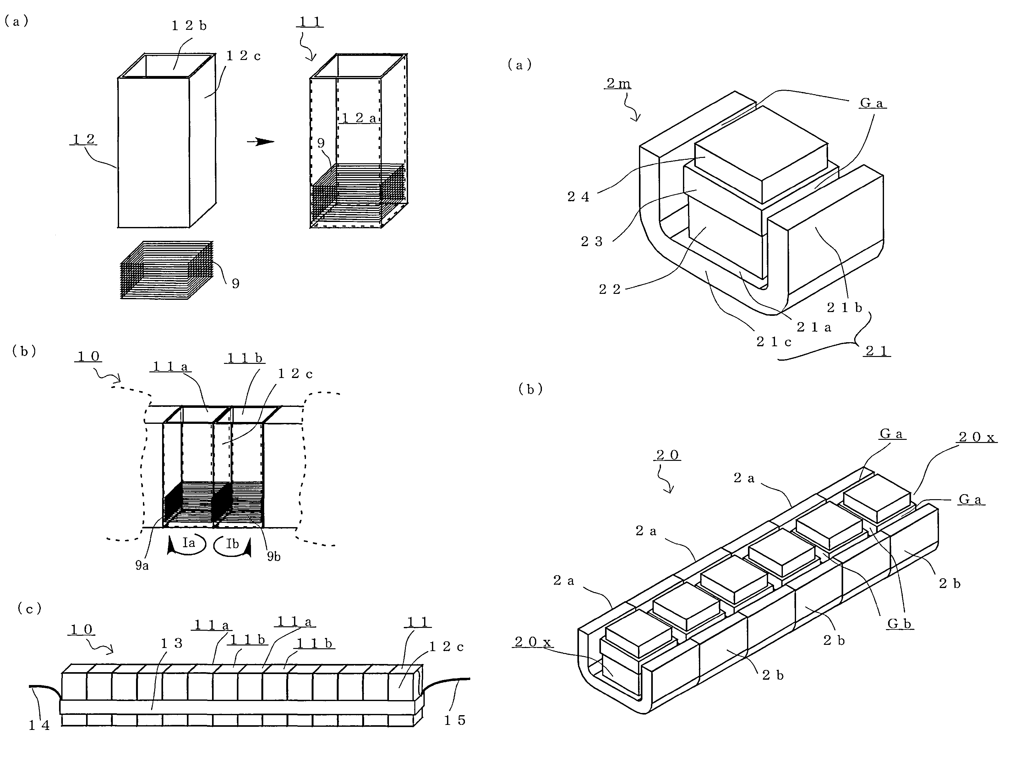
[0075]FIGS. 5A and 5B are views illustrating a magnetic circuit 20 used in the loudspeaker 1 according to another preferred embodiment of the present invention. FIG. 5A is a perspective view illustrating a magnetic circuit module 2m of the magnetic circuit 20, and FIG. 5B is a perspective view illustrating the magnetic circuit 20. The magnetic circuit 2 illustrated in FIGS. 5A and 5B includes six magnetic circuit modules 2m connected together. Specifically, the magnetic circuit 20 of FIGS. 5A and 5B includes three magnetic circuit modules 2a and three magnetic circuit modules 2b (whose direction of magnetization is opposite to that of the magnetic circuit module 2a) alternating with each other along a single row so that adjacent magnets have different polarities.

[0076]Each magnetic circuit module 2m includes a generally rectangular flat plate 23, the main magnet 22 fixed to the bottom surface of the plate 23, the yoke 21 fixed to the bottom surface of the main magnet 22, and the rep...


PUM

PropertyMeasurementUnit
lengthaaaaaaaaaa
heightaaaaaaaaaa
widthaaaaaaaaaa

Abstract

A voice coil assembly capable of realizing a flat thin loudspeaker having a high efficiency, reduced divided vibrations, a flat frequency response, and reduced operation defects. The voice coil assembly includes a plurality of internal-winding voice coils, each including a rectangular bobbin having a rectangular cross section and defining a rectangular space therein and an internal rectangular coil fixed to an inner wall surface of the rectangular bobbin defining the rectangular space, wherein an outer wall surface of the rectangular bobbin of one internal-winding voice coil is adhered and fixed to an outer wall surface of the rectangular bobbin of another internal-winding voice coil.

Description

BACKGROUND OF THE INVENTION[0001]1. Field of the Invention[0002]The present invention relates to a loudspeaker including a magnetic circuit using a plurality of magnets, and a voice coil assembly using bobbins and coils. More particularly, the present invention relates to a flat thin loudspeaker with a small overall height.[0003]2. Description of the Related Art[0004]Some electrodynamic loudspeakers for converting audio signals to sound employ flat diaphragms in order to realize a loudspeaker having a small overall height including the magnetic circuit. With a flat diaphragm, as compared with a cone diaphragm, the overall height of the loudspeaker will be small, but the loudspeaker is likely to have insufficient rigidity for vibrating as an integral unit without divided vibrations. In view of this, a conventional type of loudspeaker includes a bobbin fixed to a flat diaphragm and including a plurality of voice coils, wherein the flat diaphragm is driven by the plurality of voice coi...

Claims


Application Information

Patent Timeline
Patent Type & Authority Patents(United States)
IPC IPC(8): H04R25/00
CPCH04R9/045H04R31/00H04R9/06Y10T29/4908Y10T29/49005
Inventor SADAIE, KOICHIKUMO, HIROYASUTOYOSHIMA, YOSHIHIDENAGAOKA, SATOFUMIUJIMOTO, YOSHINORIABE, KOUICHI
Owner ONKYO KK
Why Eureka
Try Eureka