Elective service indicator based on pulse count for implantable device

a technology of implantable devices and pulse counts, which is applied in electrotherapy, heart stimulators, therapy, etc., can solve the problems of common unrechargeable, premature replacement, and added unnecessary stress and trauma to patients, and achieves the effect of reducing the risk of cardiac arres

Active Publication Date: 2010-12-07
CVRX
View PDF21 Cites 119 Cited by
  • Summary
  • Abstract
  • Description
  • Claims
  • Application Information

AI Technical Summary

Problems solved by technology

Such batteries are commonly not rechargeable, and their life expectancy may be less than the life expectancy of the patient in which the device is implanted.
Premature replacement can add unnecessary stress and trauma to the patient due to the surgery required to explant the device.
However, delaying replacement of the battery could mean that the power source depletes to a level where the device cannot function as intended.
One of the challenges with monitoring battery life for pacemakers and ICDs is that these devices deliver variable therapies, often having an on-demand or as-needed therapy schedule.
Because the therapies delivered by these devices are variable and not consistent over time, power consumption is unpredictable.
While such a replacement period is simple to calculate, the device is often replaced very prematurely.
Therefore, the power consumed by these devices can vary over the lifetime of the device.
As a result, an undesirably wide margin of error in the battery life prediction (the worst-case scenario) must be used to guard against these eventualities, thereby forcing premature surgical replacement of the implanted device and its battery in many cases, with the attendant risks of complications to the patient.
As the battery nears the end of its useful life, the battery voltage will begin to decline at a greater rate, often dramatically with a sharp drop-off in voltage.
However, such a battery creates a problem for a battery longevity monitor using the voltage of the battery to determine the longevity of the battery.
Since the battery voltage remains relatively constant over most of the life of the battery, it is difficult to predict whether the battery is in the early part of the relatively flat voltage curve or nearing the end of the relatively flat voltage curve.
The difference, of course, can mean a dramatic difference in the predicted longevity of the battery.
A further drawback to monitoring battery voltage and / or impedance to determine battery life is that the tolerances in battery voltage measurements as well as battery impedance may have such a wide variance in tolerances so as to render meaningless any estimation for battery replacement based on measurements of small changes in these values.
Many implantable devices are thus prematurely explanted based upon these inadequate measurements.
Unfortunately, the expected variability of the capacitor value over the lifetime of an implanted pacemaker, which may be ten or more years, leads to a loss of accuracy in the prediction of an appropriate time for battery replacement.
This technique clearly provides at best an approximation, and is inherently subject to a greater probability of inaccuracy than the energy consumption technique.

Method used


Image

  • Elective service indicator based on pulse count for implantable device
  • Elective service indicator based on pulse count for implantable device
  • Elective service indicator based on pulse count for implantable device

Examples


Embodiment Construction

[0022]The following detailed description should be read with reference to the drawings in which similar elements in different drawings are numbered the same. The drawings, which are not necessarily to scale, depict illustrative embodiments and are not intended to limit the scope of the invention.

[0023]In the following detailed description of the present invention, numerous specific details are set forth in order to provide a thorough understanding of the present invention. However, it will be apparent to one skilled in the art that the present invention may be practiced without these specific details. In other instances, well-known methods, procedures, and components have not been described in detail so as to not unnecessarily obscure aspects of the present invention.

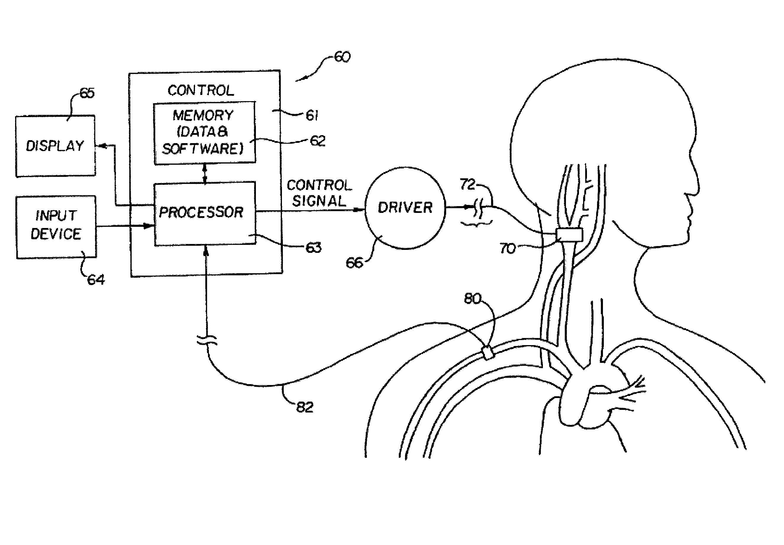
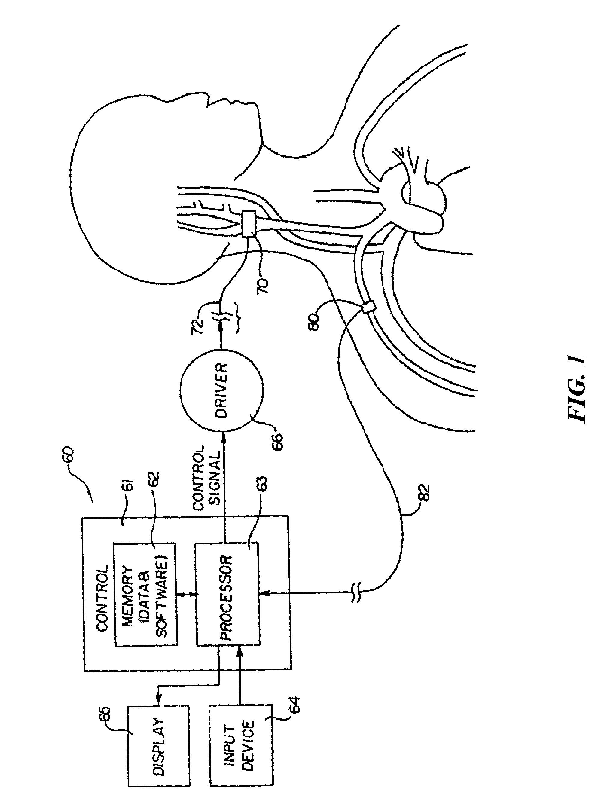
[0024]The present invention is suitable for use with various medical devices such as tissue stimulation devices, systems and methods, as well as monitoring devices. Tissue stimulation therapies can be used to stimulate ...


PUM


Abstract

The present invention is an implantable tissue stimulation therapy system, comprising an implantable tissue stimulation device including a power source of a known stored energy amount, a programmer communicably coupled to the device and adapted to propose one or more therapy parameters for the device, each therapy parameter having a known energy consumption associated therewith, wherein a predicted elective service date of the power source based on the one or more proposed therapy parameters and the known energy amount of the power source is automatically determined, and a display communicatively coupled to the activation device, the display being configured to indicate the predicted elective power source service date to an operator, wherein the operator may choose to select the one or more proposed therapy parameters based on the indicated predicted elective service date and the selected one or more therapy parameters are transmitted to the device.

Description

RELATED APPLICATION[0001]The present application claims the benefit of U.S. Provisional Application No. 60 / 951,114, filed Jul. 20, 2007, the disclosure of which is incorporated by reference herein.FIELD OF THE INVENTION[0002]The present invention relates generally to implantable medical devices. More specifically, the present invention relates to a device and method for indicating when the power source of an implantable device is in need of service.BACKGROUND OF THE INVENTION[0003]Implantable medical devices typically rely on implanted power sources, such as a battery. Such batteries are commonly not rechargeable, and their life expectancy may be less than the life expectancy of the patient in which the device is implanted. Therefore the device may need to be explanted from the patient in order to change the power source. Determining the correct time to replace the battery is important for a number of reasons. Premature replacement can add unnecessary stress and trauma to the patien...

Claims


Application Information

Patent Timeline
Patent Type & Authority Patents(United States)
IPC IPC(8): A61N1/378A61N1/37
CPCA61N1/37235A61N1/37252A61N1/36114A61N1/3708A61N1/37247A61N1/378
Inventor CROWLEY, TOMHAGEN, JEFF
Owner CVRX
Why Eureka
Try Eureka