Conveyor tensioning system

a technology of conveyor belt and tensioning system, which is applied in the direction of conveyors, conveyor parts, transportation and packaging, etc., can solve the problems of product positioning on the conveyor belt being “tacky”, unsanitary conditions, and problems such as the operation of such cooling tunnels, and achieves high speed, easy adjustment of tension, and efficient structure

Inactive Publication Date: 2010-12-14
SCHEBLER
View PDF9 Cites 13 Cited by
  • Summary
  • Abstract
  • Description
  • Claims
  • Application Information

AI Technical Summary

Benefits of technology

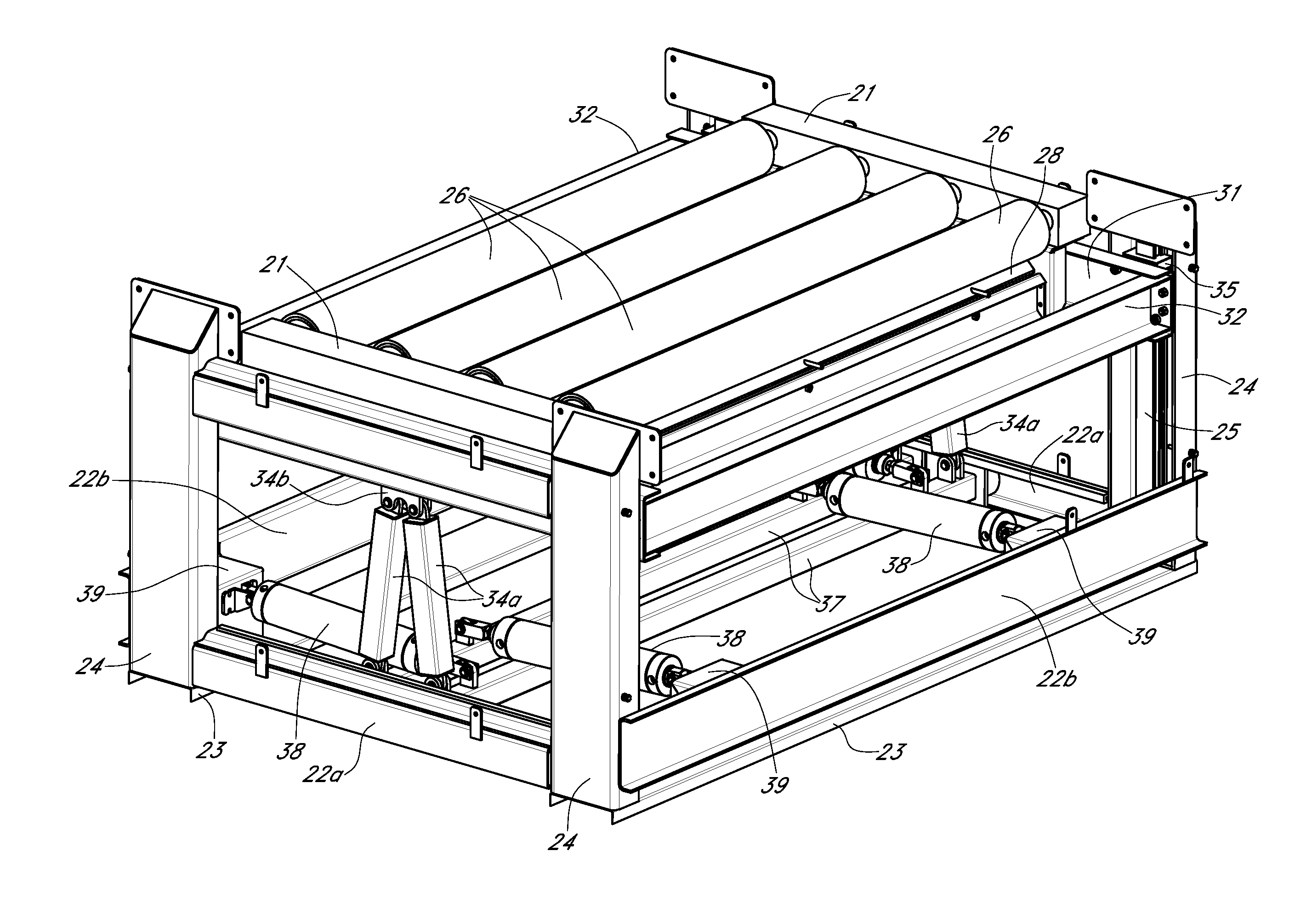
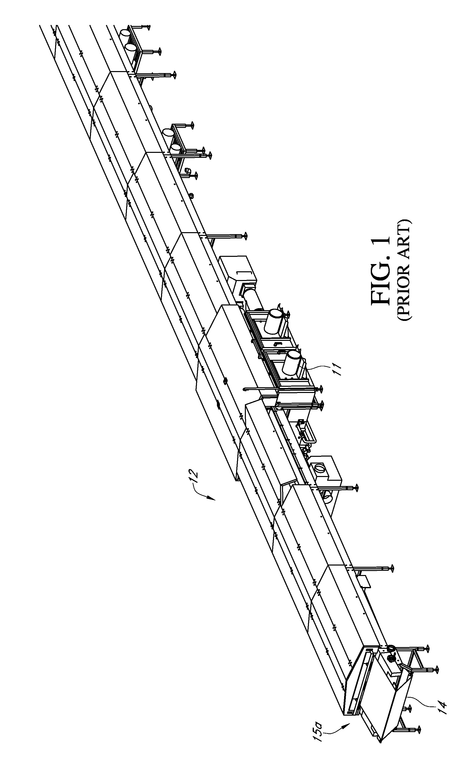
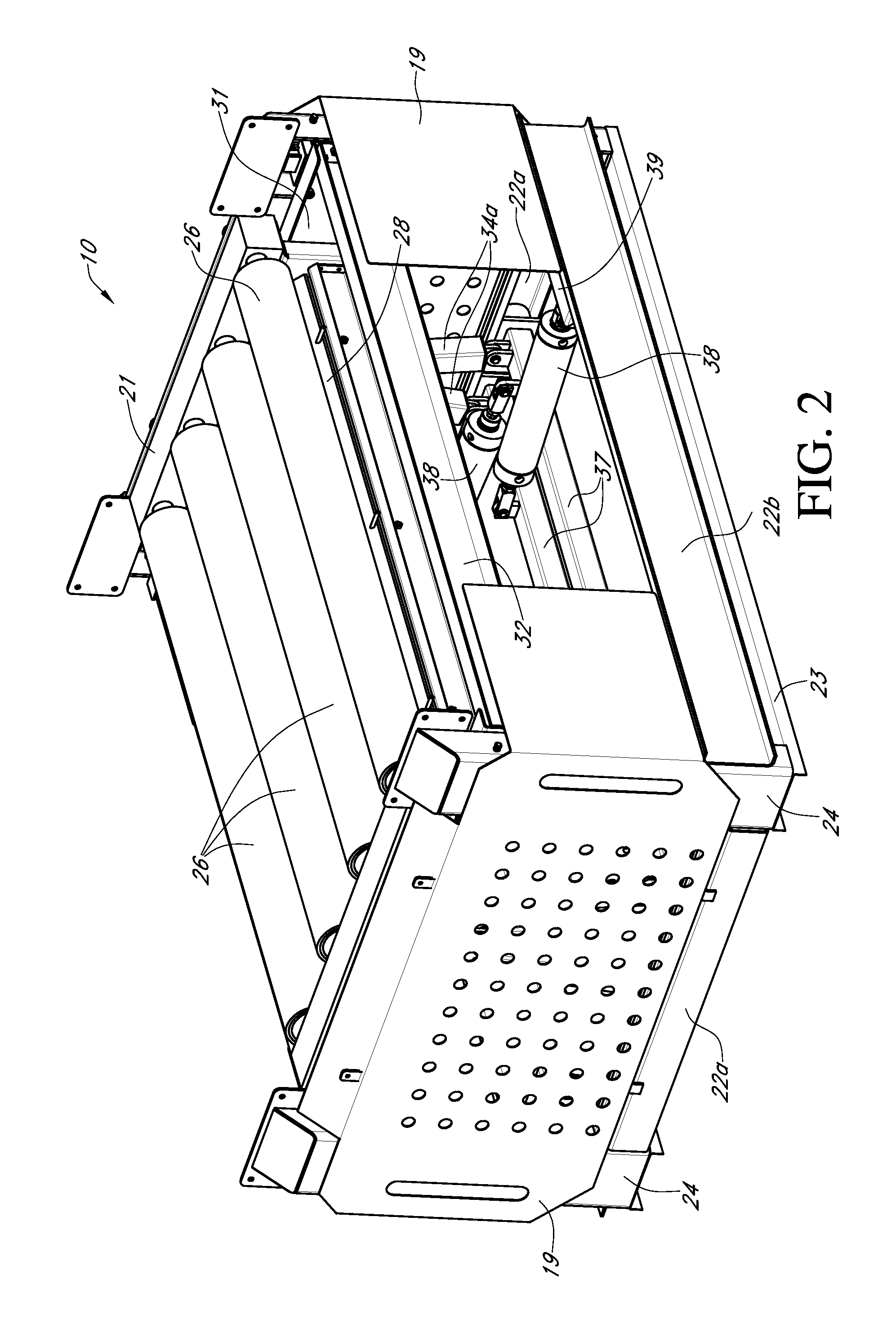
[0009]The conveyor tensioning system provides an efficient structure to easily adjust the tension on a conveyor belt and placement of scrapers on the return roller. The exemplary embodiment as pictured herein is especially suited to applications of cooling tunnels used in the manufacture of food products, and in particular to for use in high speed production of food products. The cooling tunnel as pictured herein, to which the conveyor tensioning system may be applied, is used for the cooling of baked products and the like prior to subsequent operations such as stacking or cutting and frying.

Problems solved by technology

Most clean-in-place systems and / or tensioning system are positioned on the lower portion of the conveyor system since that portion of the conveyor system is not designed to engage the product.
Problems are encountered in the operation of such cooling tunnels, particularly with high capacity tunnels providing for high speed movement of the product through the tunnel and for high velocity of cooling gas flow.
In such tunnels, the conveyor system may collect and / or trap food particles creating a potentially unsanitary condition.
This issue is especially acute in the conveyor return portion of the cooling tunnel as it is typically positioned underneath the main conveyor.
This is especially the case in situations where the product positioned on the conveyor belt is “tacky,” (e.g., products such as caramel, sugar solutions, and chocolate nougat), which have a tendency to stick to or collect on the food processing equipment.
Contact of a tacky material with the conveyor belt often results in the transfer and / or accumulation of the tacky material on the conveyor return rollers.
Accumulation or transfer of the material onto the conveyor return rollers may inhibit proper operation of the conveyor belt, contaminate the conveyor belt and interfere with maintaining the proper tension on the conveyor belt.

Method used


Image

  • Conveyor tensioning system
  • Conveyor tensioning system
  • Conveyor tensioning system

Examples


Embodiment Construction

[0025]Before the various embodiments of the present invention are explained in detail, it is to be understood that the invention is not limited in its application to the details of construction and the arrangements of components set forth in the following description or illustrated in the drawings. The invention is capable of other embodiments and of being practiced or of being carried out in various ways. Also, it is to be understood that phraseology and terminology used herein with reference to device or element orientation (such as, for example, terms like “front”, “back”, “up”, “down”, “top”, “bottom”, and the like) are only used to simplify description of the present invention, and do not alone indicate or imply that the device or element referred to must have a particular orientation. In addition, terms such as “first”, “second”, and “third” are used herein and in the appended claims for purposes of description and are not intended to indicate or imply relative importance or s...


PUM


Abstract

A method and apparatus for a conveyor tensioning system comprising a main frame with at least one main frame roller pivotally mounted thereto for engagement with a conveyor belt. A moveable frame is engaged with the main frame at an engagement interface such that the position of the moveable frame with respect to the main frame may be adjusted in at least one dimension. The moveable frame also includes at least one moveable frame roller pivotally mounted thereto for engagement with a conveyor belt. The position of the moveable frame with respect to the main frame may be actuated by hydraulic cylinders or other mechanical systems. As the distance between the main frame and moveable frame increases, the tension on the belt also increases.

Description

CROSS REFERENCE TO RELATED APPLICATIONS[0001]Applicant claims priority under 35 U.S.C. §119(e) of provisional U.S. Patent App. No. 61 / 070,532 filed on Mar. 24, 2008, which is incorporated by reference herein in its entirety.FIELD OF INVENTION[0002]Food processing equipment and more particularly, a conveyor for manufacture of food products, and in particular to a new and improved tensioning system for use with conveyor systems in the production of food products.STATEMENT REGARDING FEDERALLY SPONSORED RESEARCH OR DEVELOPMENT[0003]No federal funds were used to develop or create the invention disclosed and described in the patent application.REFERENCE TO SEQUENCE LISTING, A TABLE, OR A COMPUTER PROGRAM LISTING COMPACT DISK APPENDIX[0004]Not ApplicableAUTHORIZATION PURSUANT TO 37 C.F.R. §1.171 (d)[0005]A portion of the disclosure of this patent document contains material which is subject to copyright and trademark protection. The copyright owner has no objection to the facsimile reproduc...

Claims


Application Information

Patent Timeline
Patent Type & Authority Patents(United States)
IPC IPC(8): B65G23/44
CPCB65G15/60B65G23/44B65G47/66
Inventor COOLEY, NJELL J.GRILLOT, TIMOTHY A.JONES, LARRY D.
Owner SCHEBLER
Why Eureka
Try Eureka