Paper sheet storing apparatus

a paper storage and paper sheet technology, applied in the direction of coin/currency accepting devices, thin material processing, instruments, etc., can solve the problems of not considering the case of simultaneous accumulation of multiple different types of paper sheets in different sizes in one paper, the rear end of the paper sheet along the conveying direction to be lifted up, paper jam or other relevant trouble,

Inactive Publication Date: 2010-12-14
HITACHI OMRON TERMINAL SOLUTIONS CORP
View PDF17 Cites 9 Cited by
  • Summary
  • Abstract
  • Description
  • Claims
  • Application Information

AI Technical Summary

Benefits of technology

[0009]In a paper sheet storing apparatus constructed to collect and accumulate multiple different types of paper sheets, there would thus be a demand for reducing the potential for paper jams and relevant troubles and ensures stable accumulation of paper sheets.
[0026]In the paper sheet storing apparatus of this embodiment, the rear ends of the paper sheets fed by the feeder into the paper sheet cartridge are hit by the hitting member to drop the paper sheets down into the paper sheet cartridge below the feeder. This arrangement effectively prevents paper sheets newly and subsequently conveyed into the paper sheet cartridge from colliding with paper sheets conveyed and accumulated in advance in the paper sheet cartridge.

Problems solved by technology

The technique of the above cited reference, however, does not consider the case of such simultaneous accumulation of multiple different types of paper sheets (for example, banknotes or bills) in different sizes in one paper sheet cartridge.
In the case of accumulation of smaller size paper sheets in the paper sheet cartridge of this design, however, there may be a relatively large clearance formed between a side wall of the paper sheet cartridge and the paper sheets accumulated therein.
A front end of the paper sheet along its conveying direction may be stuck in this clearance and cause a rear end of the paper sheet along its conveying direction to be lifted up.
This may lead to a paper jam or another relevant trouble.

Method used


Image

  • Paper sheet storing apparatus
  • Paper sheet storing apparatus
  • Paper sheet storing apparatus

Examples


modified example 1

D1. Modified Example 1

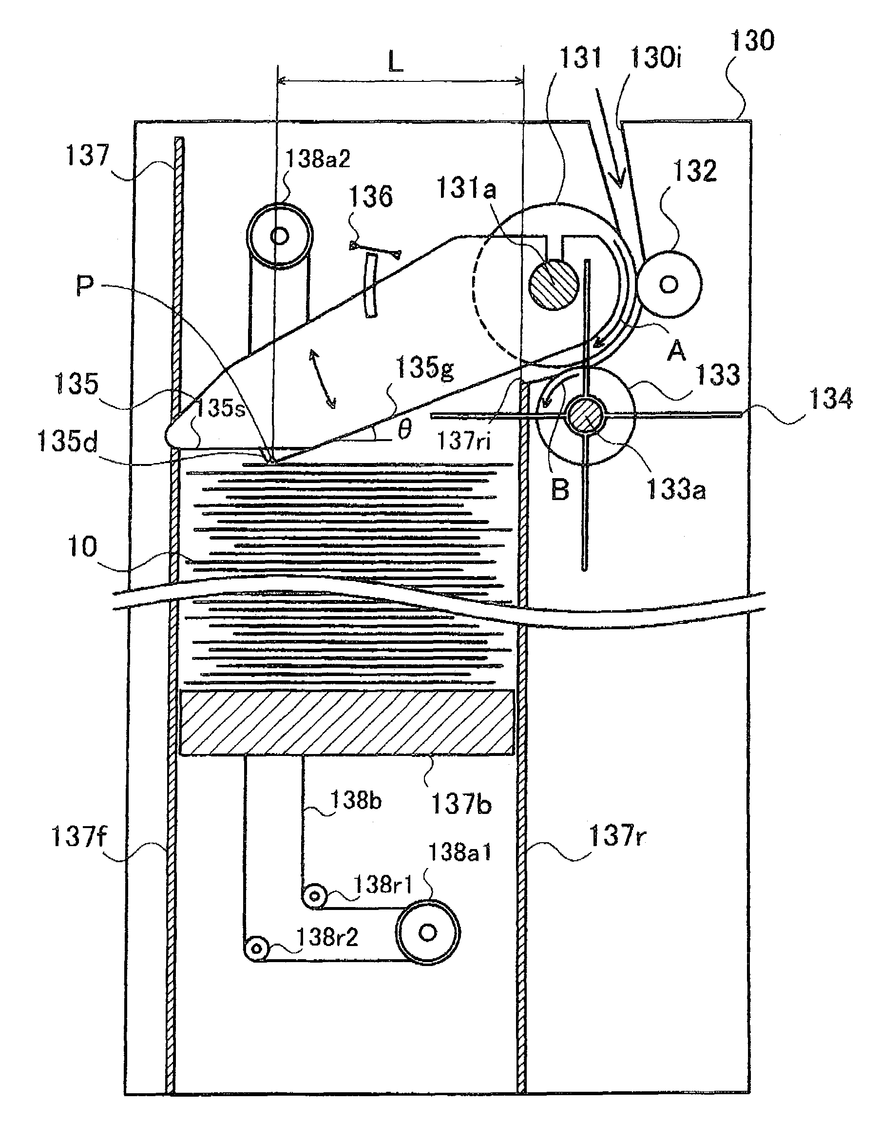
[0081]FIG. 5 is a side sectional view showing the schematic structure of another reject cartridge 130A in one modified example. The reject cartridge 130A of the modified example has a similar structure to that of the reject cartridge 130 of the embodiment, except a stack guide 135A provided in place of the stack guide 135.

[0082]In the reject cartridge 130A of the modified example, the stack guide 135A has a pressure roller 135r rotatable in the conveying direction of the rejected bills 10, in place of the projection 135d formed on the stack guide 135 in the reject cartridge 130 of the embodiment. The pressure roller 135r is extended downward from a lower face 135s of the reject cartridge 130A and presses down the rejected bills 10 collected and accumulated in a storage cartridge 137. A distance La between the pressure roller 135r and a 1st side wall 137r is set to be less than the width WSmin of the minimum size rejected bill 10 in the widthwise direction shown...

modified example 2

D2. Modified Example 2

[0085]FIG. 6 is a side sectional view showing the schematic structure of still another reject cartridge 130B in another modified example. The reject cartridge 130B of this modified example has a similar structure to that of the reject cartridge 130 of the embodiment, except a stack guide 135B provided in place of the stack guide 135.

[0086]In the reject cartridge 130B of the modified example, the stack guide 135B does not have the projection 135d provided on the stack guide 135 in the reject cartridge 130 of the embodiment. The top surface of the rejected bills 10 accumulated in the storage cartridge 137 is pressed by a lower face 135s of the stack guide 135B. A distance Lb between an edge 135se of the lower face 135s of the stack guide 135B and a 1st side wall 137r is set to be less than the width WSmin of the minimum size rejected bill 10 in the widthwise direction shown in FIG. 4(c).

[0087]Like the reject cartridge 130 of the embodiment, the reject cartridge 1...

modified example 3

D3. Modified Example 3

[0088]In the cash handling apparatus 101 and the reject cartridge 130 of the embodiment, the conveying direction of the rejected bills 10 is set to the widthwise direction of the rejected bills 10. This is, however, neither restrictive nor essential. The conveying direction of the rejected bills 10 may alternatively be set to the longitudinal direction of the rejected bills 10. In this alternative arrangement, the distance L between the projection 135d of the stack guide 135 and the 1st side wall 137r in the reject cartridge 130 is set to be less than the length WLmin of the minimum size rejected bill 10 in the longitudinal direction shown in FIG. 4(c).


PUM

PropertyMeasurementUnit
circumferenceaaaaaaaaaa
sizesaaaaaaaaaa
angleaaaaaaaaaa

Abstract

A paper sheet storing apparatus is configured to collect and accumulate multiple different types of paper sheets in different sizes. The paper sheet storing apparatus has: a paper sheet cartridge configured to have a feeder provided on a side wall thereof for externally feeding paper sheets and arranged to accumulate and keep the paper sheets therein; and a stack guide member configured to introduce the paper sheets, which are fed by the feeder into the paper sheet cartridge, downward in the paper sheet cartridge and to press down surface of an uppermost paper sheet located on a top of the paper sheets accumulated and kept in the paper sheet cartridge. The stack guide member is structured in a specific shape to enable the surface of the uppermost paper sheet to be pressed downward in a vertical direction, with regard to all the multiple different types of paper sheets. This arrangement effectively reduces the potential for paper jams and relevant troubles and ensures stable accumulation of paper sheets.

Description

BACKGROUND OF THE INVENTION[0001]1. Field of the Invention[0002]The present invention relates to a paper sheet storing apparatus, and more specifically to a paper sheet storing apparatus configured to collect and accumulate multiple different types of paper sheets in different sizes.[0003]2. Description of the Related Art[0004]Automatic teller machines are generally used for the users' financial transactions including cash deposits and withdrawals in financial facilities and organizations. The automatic teller machine is equipped with a paper sheet handling system designed to handle diversity of paper sheets including banknotes or bills and forms and slips. The paper sheet handling system includes a paper sheet storing apparatus configured to collect and accumulate externally fed paper sheets. The paper sheet storing apparatus has a paper sheet cartridge to accumulate and keep the paper sheets therein.[0005]In the paper sheet storing apparatus, paper sheets newly and subsequently co...

Claims


Application Information

Patent Timeline
Patent Type & Authority Patents(United States)
IPC IPC(8): B65H29/38
CPCB65H31/18B65H31/22B65H31/26G07D11/0081B65H2301/4223B65H2404/1114B65H2511/21B65H2513/40B65H2553/612B65H2701/1912B65H2220/02B65H2220/11G07D11/40B65H2553/61
Inventor NAGURA, AKIHIRONAKATA, YASUHIRO
Owner HITACHI OMRON TERMINAL SOLUTIONS CORP
Why Eureka
Try Eureka