Hub assembly for a tilting vehicle suspension

a technology for vehicle suspension and hub assembly, which is applied in the direction of steering linkages, transportation and packaging, and bicycles, etc., can solve the problems of vehicle slipping out of the direction, centrifugal load, and less fuel-efficient than three-wheel motor vehicles, so as to improve the stability of the vehicle, enhance the steering control, and increase the leverage available for tilting

Active Publication Date: 2010-12-14
SWAY MOTORSPORTS INC
View PDF41 Cites 30 Cited by
  • Summary
  • Abstract
  • Description
  • Claims
  • Application Information

AI Technical Summary

Benefits of technology

[0007]In this regard, the present invention provides a suspension system for a wheeled vehicle that allows for the vehicle body to be tilted by the operator in a manner that greatly enhances the stability of the vehicle while producing a fun vehicle to operate. Further, the hubs that are employed to create the vertical components of the four bar suspension arrangement are configured in a manner that separates both the steering and tilting axes, spacing them apart from one another to increase the leverage available for tilting while allowing enhanced steering control.
[0008]In the most general terms, a hub is provided that includes an inboard side and an outboard side such that the tilting pivots are positioned inboard and the steering pivots are positioned outboard. This arrangement allows for the optimum placement of the pivot axis for steering as close to the wheel as possible, even directly within the rim of the wheel, where possible. While the pivot point of the suspension linkage is optimally positioned a few inches inboard relative to the wheels thereby increasing the lever arm relative to the tilt of the wheel. This placement this allows a greater lever arm sticking out perpendicularly from the wheel on which to apply a downward force, thereby causing the wheels and thus the entire linkage to tilt. When the linkage pivots are closer in towards the center of the vehicle, the lever arms are much longer and the downward force from the foot of the rider has an amplified effect on the tilt of the vehicle. As a consequence, while the footpads rise and fall more dramatically as the linkage articulates, which takes a little getting used to, the rider is able to create substantial tilting force with less force application to the footpads.
[0009]Further, by separating the two axes, the pivot points within the suspension are then attached using shoulder bolts and thrust bearings rather than ball joints. This arrangement makes the linkage connection points much more rigid. This also allows the steering geometry to be arranged such that the steering axis is tilted relative to a vertical plane so that it is aligned along an axis that intersects with the center point where the wheel contacts the ground.
[0010]Accordingly, it is an object of the present invention to provide a hub for a tilting vehicle suspension that separates the tilting and steering axes from one another. It is a further object of the present invention to provide a hub for use in a tilting vehicle suspension that facilitates for greater vehicle load-bearing capacity by reducing the overall foot pressure required to maintain the vehicle tilt at all speed ranges and during cornering maneuvers.

Problems solved by technology

Currently, most motor vehicles on the highways are four-wheel vehicles that are typically larger, heavier and less fuel-efficient than three-wheel motor vehicles.
Despite the advantages that three wheeled vehicles enjoy over four-wheel vehicles, the main drawback of a three-wheel vehicle is that during a turn the centrifugal load of the vehicle is supported by only a single outside wheel rather than two, as would be the case in a four-wheeled vehicle.
In this regard, the centrifugal force tends to overload the outside tire, causing the vehicle to slip out of the direction of the turn, unless some additional means of compensation is provided.
Further, the three-wheel geometry allows the force vector associated with the vehicle's center of gravity to quickly fall outside the wheelbase of the vehicle causing an unstable condition whereby the risk of overturning the vehicle greatly increases.
Such an arrangement creates several distinct problems.
First, because the steering pivot must be positioned as close to the center of the wheel as possible, the trade off is that there is a greatly reduced distance of travel available for the foot controlled tilting function.
As a result, a rider is required to apply a great deal of force with their feet to maintain the vehicle tilt through turns.
Further, should a rider turn the vehicle too quickly, the force required to tilt the vehicle may increase so quickly that the rider may not be able to maintain the tilt, ultimately losing tilt control and flipping the vehicle.
Secondly, when using ball joints within a four bar suspension to allow both tilting and steering, the resultant steering axes are nearly vertical, greatly reducing steering performance and leading to bump steering effects for side mounted wheels.
The problem is that this configuration is not possible if ball joints are used because the parallelogram four-bar linkage does allow proper vehicle tilting if it is wider at the bottom than at the top.

Method used


Image

  • Hub assembly for a tilting vehicle suspension
  • Hub assembly for a tilting vehicle suspension
  • Hub assembly for a tilting vehicle suspension

Examples


Embodiment Construction

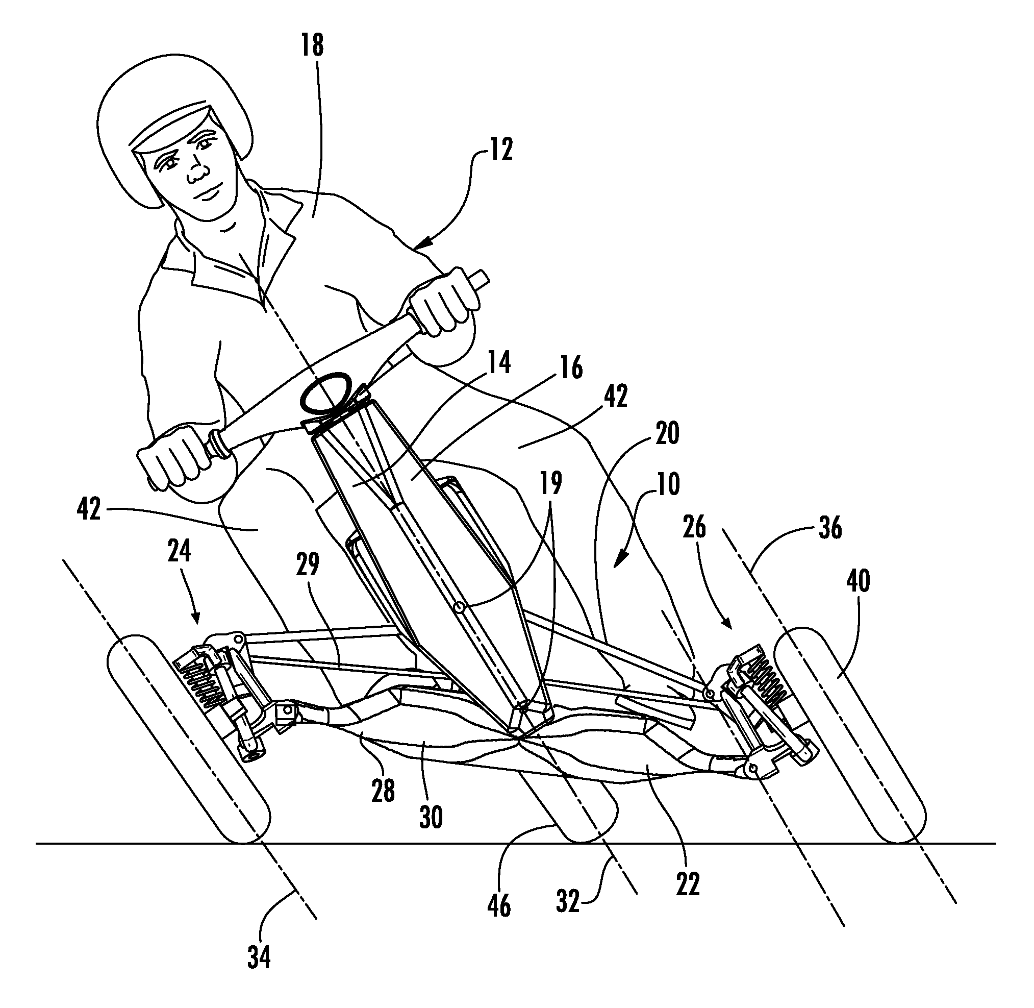
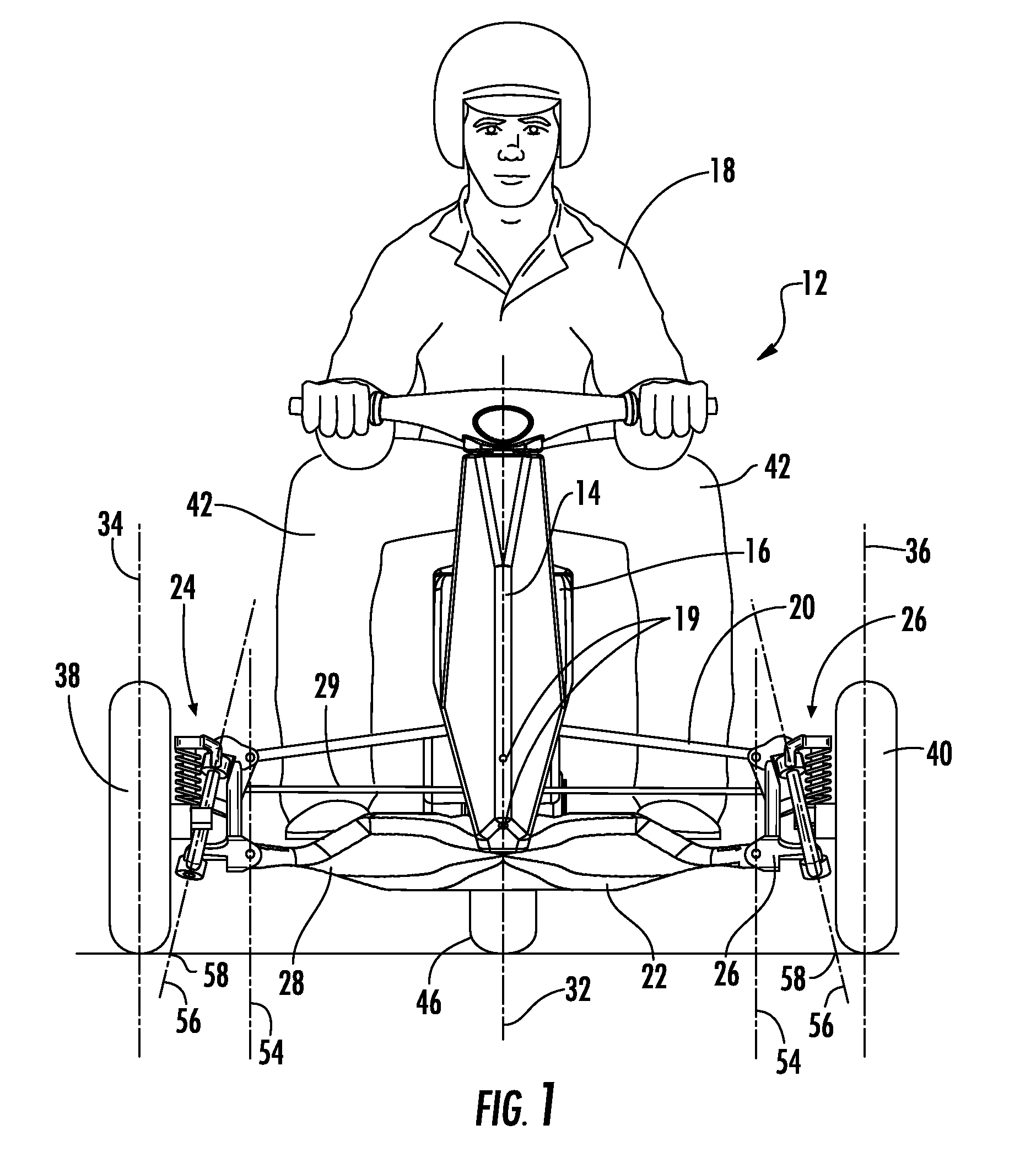
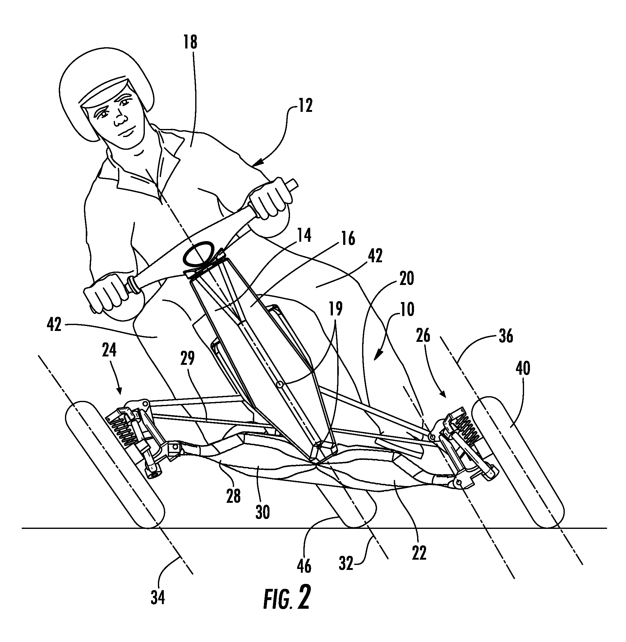
[0020]Now referring to the drawings, the suspension assembly for a tilting vehicle is shown and generally illustrated in the figures. FIGS. 1-2 depict the suspension assembly 10 employing hubs as taught by the present invention and they are installed at the front of a three-wheeled tilting vehicle 12. FIGS. 3-6 depict detailed views of the hubs in accordance with the present invention. Finally, FIG. 7 depicts the improved suspension geometry that is achieved through the hubs and suspension of the present invention.

[0021]As can be seen in FIGS. 1 and 2, the suspension system 10 of the present invention is depicted on a tilting vehicle 12 that is in an upright and a tilted position and is depicted in the context of a wheeled vehicle. In general terms, the suspension assembly 10 of the present invention includes a central frame 14 having a front, a rear and a support means 16 for a rider 18. The suspension assembly 10 can be seen attached to the front of the central frame 14 at pivots ...


PUM


Abstract

A suspension system for a vehicle is provided that allows for the vehicle body to be tilted wherein the tilt is controlled by the operator's legs in a manner that greatly enhances the stability of the vehicle while producing a fun vehicle to operate. Generally a hub is provided for use ad the vertical members in a four-bar suspension linkage that includes an inboard side and an outboard side such that the tilting pivots are positioned inboard and the steering pivots are positioned outboard. This arrangement allows for the optimum placement of the pivot axis for steering as close to the wheel as possible, even directly within the rim of the wheel, while the pivot point of the suspension linkage is optimally positioned a few inches inboard relative to the wheels thereby increasing the lever arm used to control the relative tilt of the wheel.

Description

CROSS-REFERENCE TO RELATED APPLICATIONS[0001]This application is related to and claims priority from earlier filed U.S. Provisional Patent Application No. 60 / 982,150, filed Oct. 24, 2007.BACKGROUND OF THE INVENTION[0002]The present invention relates to generally to an improved suspension system for tilting vehicles. More specifically, the present invention relates to a hub arrangement for use in a tilting vehicle suspension that improves the overall performance of the vehicle by separating the tilting and steering axes in a manner that lengthens the tilting lever arm while shortening the steering lever arm in a manner that enhances overall vehicle control.[0003]Currently, most motor vehicles on the highways are four-wheel vehicles that are typically larger, heavier and less fuel-efficient than three-wheel motor vehicles. Despite the fact that four wheeled vehicles are more common, there are several advantages to modern three-wheeled vehicles. For example, under most circumstances th...

Claims


Application Information

Patent Timeline
Patent Type & Authority Patents(United States)
IPC IPC(8): B60G21/00B62D61/06
CPCB60G7/008B60G7/02B62D9/02B62K5/05B62K5/10B60G21/007B60G2200/46B60G2204/30B60G2300/45B62K2005/001
Inventor WILCOX, JOSEPH
Owner SWAY MOTORSPORTS INC
Why Eureka
Try Eureka