LED devices for offset wide beam generation

a wide beam and led device technology, applied in outdoor lighting, semiconductor devices for light sources, lighting and heating apparatuses, etc., can solve the problems of high cost, high cost, and high cost, and achieve the effect of reducing the cost of led illumination, saving and reducing the cost of initial investmen

Active Publication Date: 2010-12-21
SIGNIFY HLDG BV
View PDF69 Cites 53 Cited by
  • Summary
  • Abstract
  • Description
  • Claims
  • Application Information

AI Technical Summary

Problems solved by technology

However they are still very expensive in lumens per dollar compared to these traditional lamp sources.
The initial investment cost of LED illumination is expensive when compared with traditional lighting means using cost per lumen as the metric.
While this may change over time, this high cost places a premium on collection and distribution efficiency of the LED optical system.
Lenses which are not coated with anti-reflective coatings also have surface losses associated with them.
Another Lumileds LED, commonly called a low dome, has a lens over the LED package to redirect the light, but it is to be noted that it has a singular distinct radius of curvature on the front surface and is not intended, nor is it suited for generating a smooth two dimensional patterned surface such as needed for illumination of a street or parking lot.
Such armatures are often complex and / or difficult to assemble.

Method used


Image

  • LED devices for offset wide beam generation
  • LED devices for offset wide beam generation
  • LED devices for offset wide beam generation

Examples


first embodiment

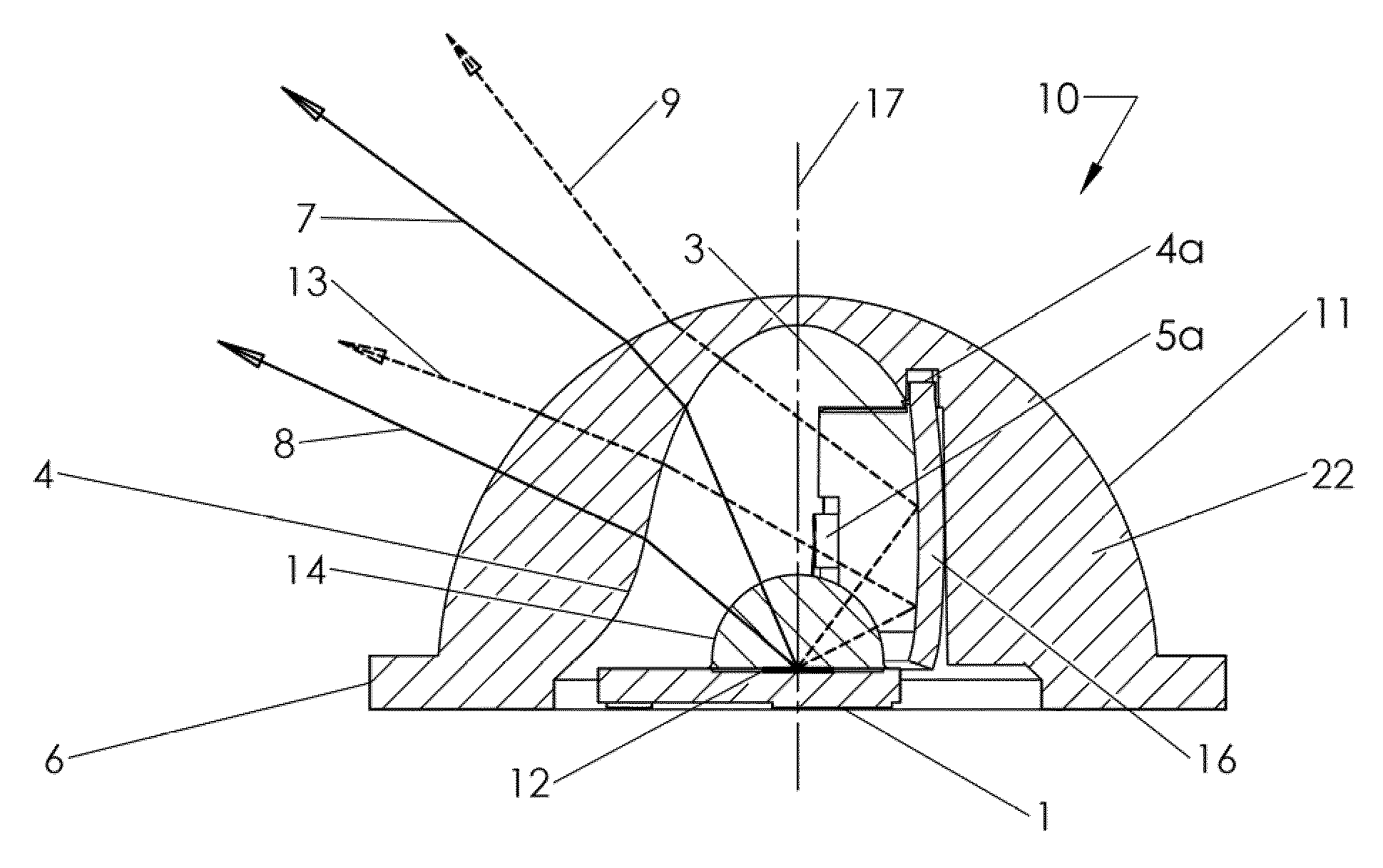
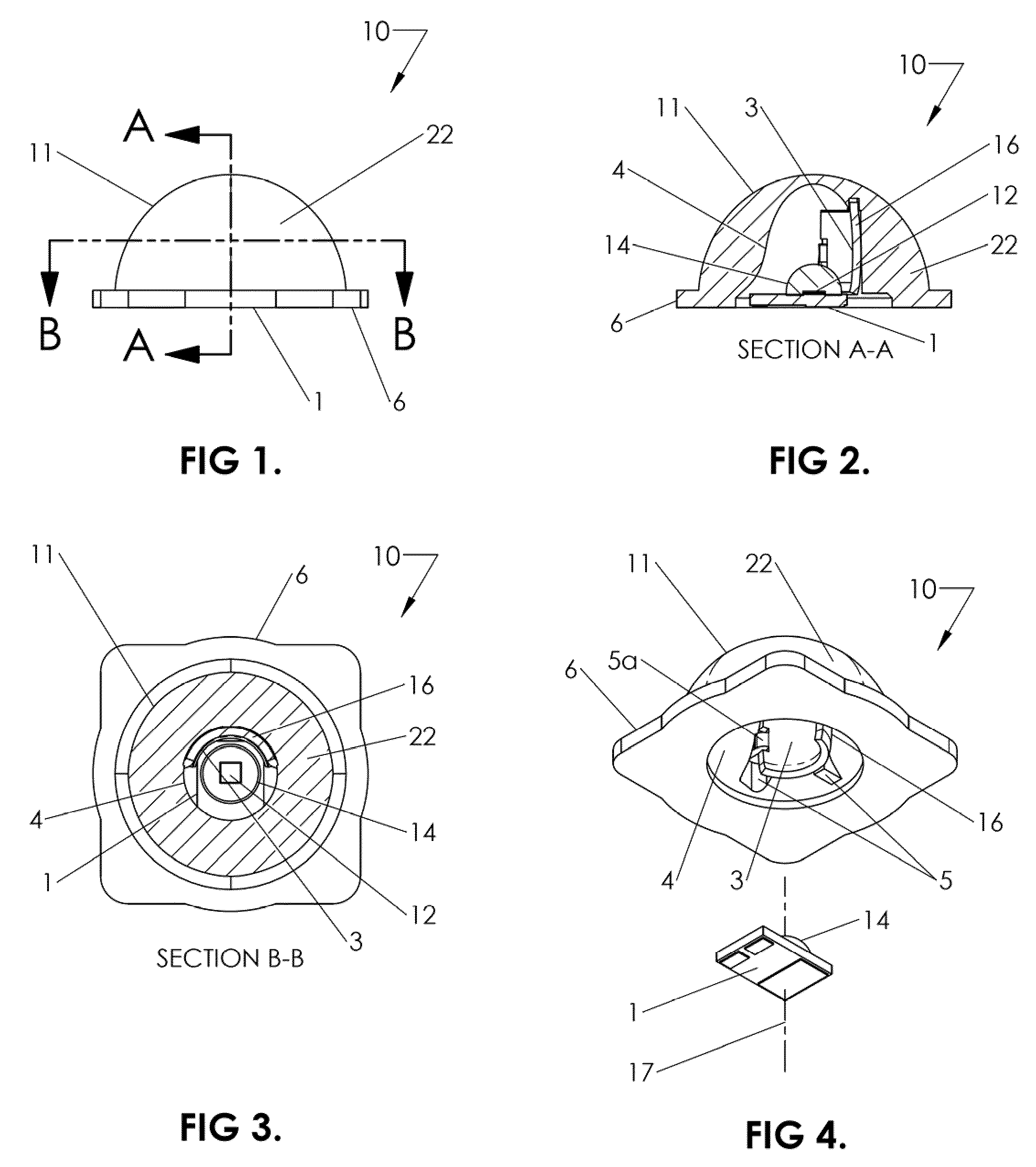
[0061]FIG. 1 illustrates a side plan view of a device 10 corresponding to the invention. Device 10 comprises an LED (light emitting diode) or LED package, the base of package 1 of which only is viewable in the view of FIG. 1 and a base 6 to an optical surface 11 of the optic 22, the outer surface 11 of which is shown in FIG. 1 as generally hemispherical. The smooth outer surface 11 of the optic 22 minimizes the amount of dust, dirt or debris that tends to lodge, stick or otherwise adhere to the optic 22, so that when device 10 is used as an exposed light source in a luminaire, it tends to shed environmental borne material that might otherwise obscure or reduce the optical transmissibility of outer surface 11 of the optic 22 over time. Thus, it must be understood that while the embodiment of FIG. 1 shows a substantially hemispherical outer surface 11, it is within the scope of the invention that the outer surface 11 could be provided with other smooth three dimensional shapes which w...

second embodiment

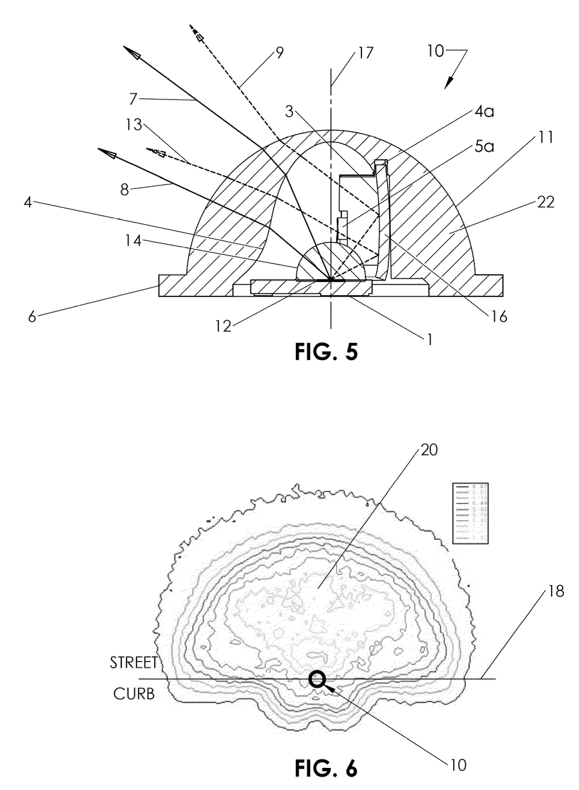
[0064]For example, in this embodiment surface 4 has a notch 4a defined in it as shown in FIG. 5 into which a post integrally extending from reflector 16 is positioned during assembly. Locating flanges 5 as best seen in FIG. 4 extend from surface 4 to provide a multiple-point guide for the lower curved portion of reflector 16. Side clips 5a extend from surface 4 to snap into matching indentations defined in the lower forward edges of reflector 16 as seen in FIGS. 4 and 5. Many different mounting and alignment schemes can be used for the assembly of reflector16 in the optic 22. An additional embodiment is shown in FIGS. 7-11b, which by no means limits the range of equivalent designs. In FIG. 4. the LED package 1 is vertically removed from the cavity in the optic 22 to show the inside detail of the optic 22. Base flange 6 as shown in FIGS. 1-5 is an optional feature of the optic 22 which is utilized for rotational mounting orientation or angular indexing.

[0065]In an alternative embodim...


PUM


Abstract

A light source is combined with an optic and a reflector. Light incident onto to the reflector is reflected with a single reflection. The reflector occupies a portion of a solid angle around the light source to the exclusion of the optic at least with respect to any optical function. The reflector directly receives a second portion of light. The optic occupies substantially all of the remaining portion of the predetermined solid angle to directly receive a first portion of light from the light source. A reflected beam from the reflector is reflected into a predetermined reflection pattern. The inner and / or outer surface of the optic is shaped to refract or direct light which is directly transmitted into the optic from the light source from a first portion of light and / or reflected into the optic from the reflector from the reflected beam into a predetermined beam.

Description

[0001]The present application is related to U.S. Provisional Patent Applications, Ser. No. 61 / 088,812 filed on Aug. 14, 2008, and 61 / 122,339 filed Dec. 12, 2008, which are incorporated herein by reference and to which priority is claimed pursuant to 35 USC 119.BACKGROUND OF THE INVENTION[0002]1. Field of the Invention[0003]The invention relates to the field of apparatus and methods for using LEDs or other light sources to generate predetermined offset wide profile two dimensional illumination patterns on a surface using a light source which has been optically modified to provide a corresponding wide profile beam or an array of multiple modified light sources.[0004]2. Description of the Prior Art[0005]Light emitting diodes (LEDs) are now being utilized for general lighting applications such as street lights, parking garage lighting, parking lots and many interior applications as well. LEDs have reached efficiency values per watt that outpace almost all traditional light sources, such...

Claims


Application Information

Patent Timeline
Patent Type & Authority Patents(United States)
IPC IPC(8): F21V33/00
CPCF21V5/04F21V13/04F21V17/101F21V17/164F21V13/02F21V7/0066F21K9/00F21W2131/103F21Y2101/02Y10S362/80F21K9/90F21Y2101/00F21K9/68F21Y2115/10F21V3/02F21V7/00
Inventor HOLDER, RONALD G.RHOADS, GREG
Owner SIGNIFY HLDG BV
Why Eureka
Try Eureka