Control apparatus and control method for hydraulically driven cooling fan

a control apparatus and hydraulically driven technology, applied in the direction of rotary clutches, fluid couplings, couplings, etc., can solve the problems of affecting the durability of hydraulic equipment, excessive load on hydraulic equipment, and impaired cooling performance, so as to reduce the peak pressure and increase the cost of the apparatus

Inactive Publication Date: 2010-12-28
KOMATSU LTD
View PDF10 Cites 9 Cited by
  • Summary
  • Abstract
  • Description
  • Claims
  • Application Information

AI Technical Summary

Benefits of technology

[0020]In view of the above state of affairs, it is an object of the present invention to reduce the peak pressure produced upon reversing the switch position of a switching valve, without stopping an engine, and without greatly modifying existing hydraulic circuitry or increasing the apparatus cost.

Problems solved by technology

However, upon the radiator or oil cooler being used for a long time, clogging with rubbish may occur, and hence the cooling performance may be impaired.
As a result, the hydraulic equipment is subjected to an excessive load, which may affect the durability of the hydraulic equipment.
Moreover, the hydraulically driven cooling fan 13 reverses while maintaining a high rotational speed, and hence the fan produces much noise upon the reversal, giving an operator an unpleasant or incongruous feeling.
An abnormal noise may also be produced by other hydraulic equipment upon the reversal, again giving the operator an unpleasant or incongruous feeling.

Method used


Image

  • Control apparatus and control method for hydraulically driven cooling fan
  • Control apparatus and control method for hydraulically driven cooling fan
  • Control apparatus and control method for hydraulically driven cooling fan

Examples


first working example

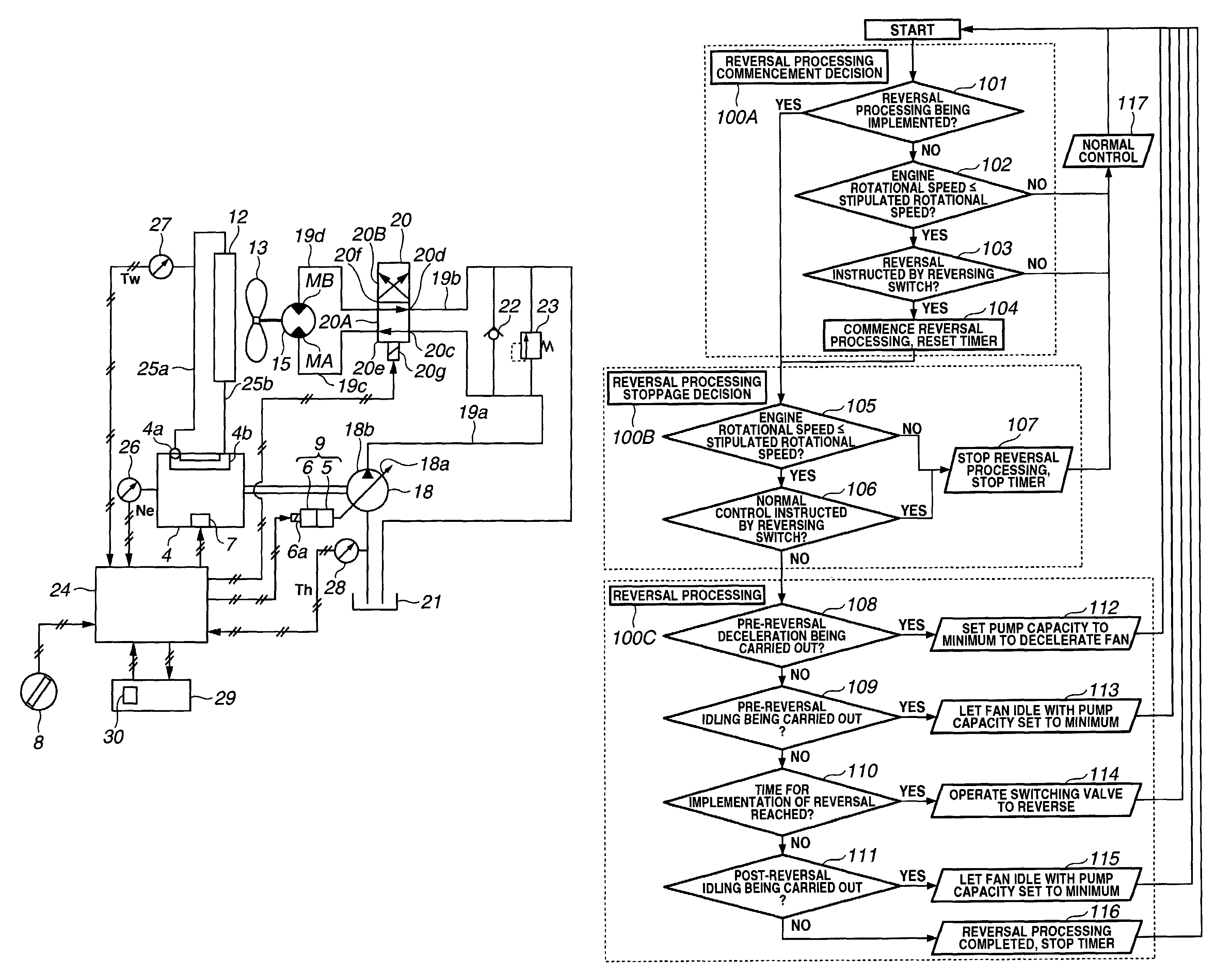
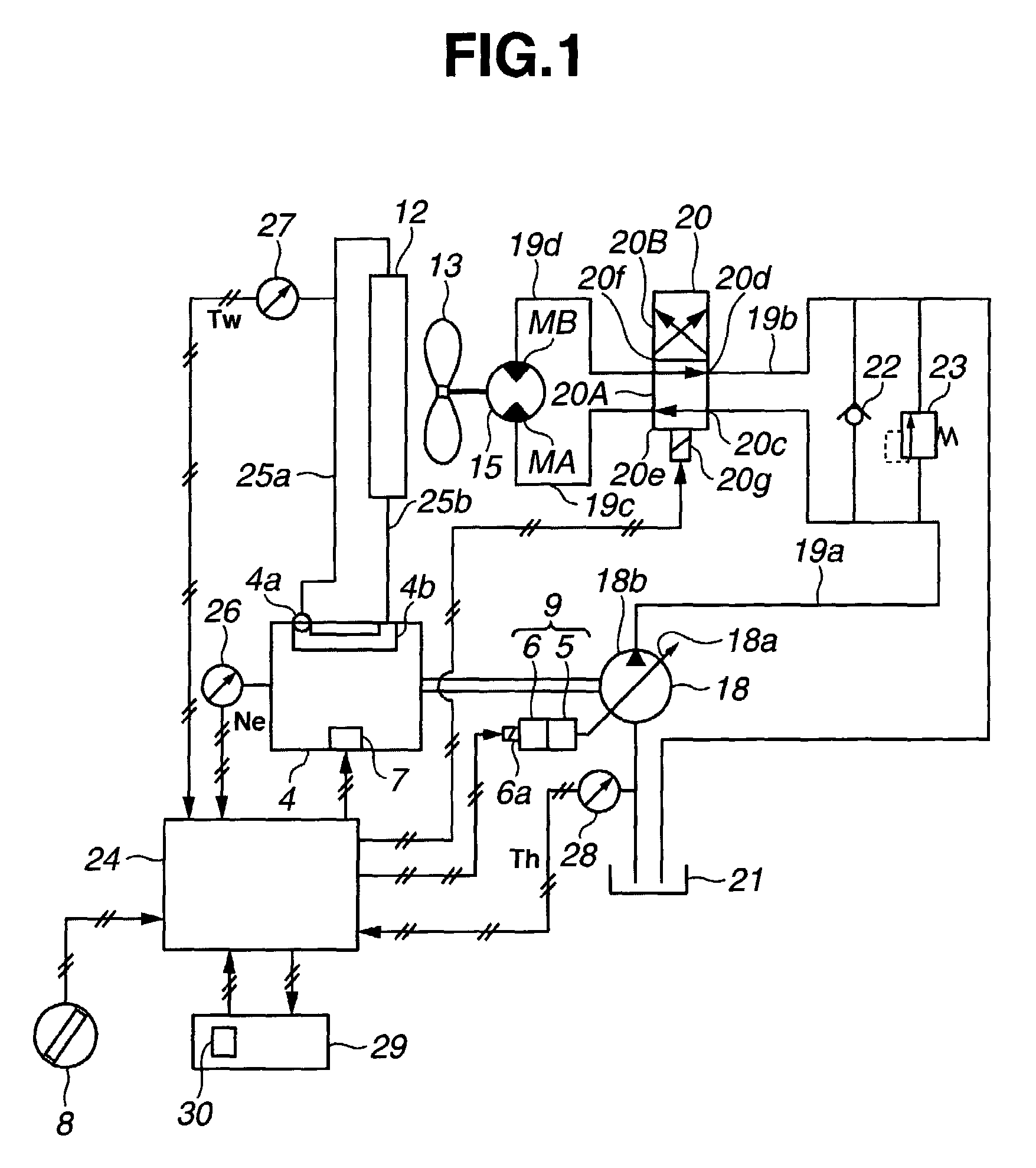
[0115]In this first working example, when the reversing switch 30 is operated so that the reversal processing commencement instruction signal is outputted, control is carried out in which, under the condition that the rotational speed Ne of the engine 4 has decreased to not more than a stipulated rotational speed, the capacity adjusting means 9 is controlled, so as to reduce the capacity of the hydraulic pump 18, and thus reduce the fan rotational speed N, and then the switch position of the switching valve 20 is reversed. Part (a) of FIG. 4 shows the relationship between the time t and the fan rotational speed N in the first working example, and part (b) of FIG. 4 shows transitions between the first reversal processing, normal control, and the second reversal processing on a time chart. That is, upon the control program being started up, reversal processing commencement decision processing 100A (steps 101 to 104) is implemented.

[0116]First, it is judged whether or not reversal proc...

second working example

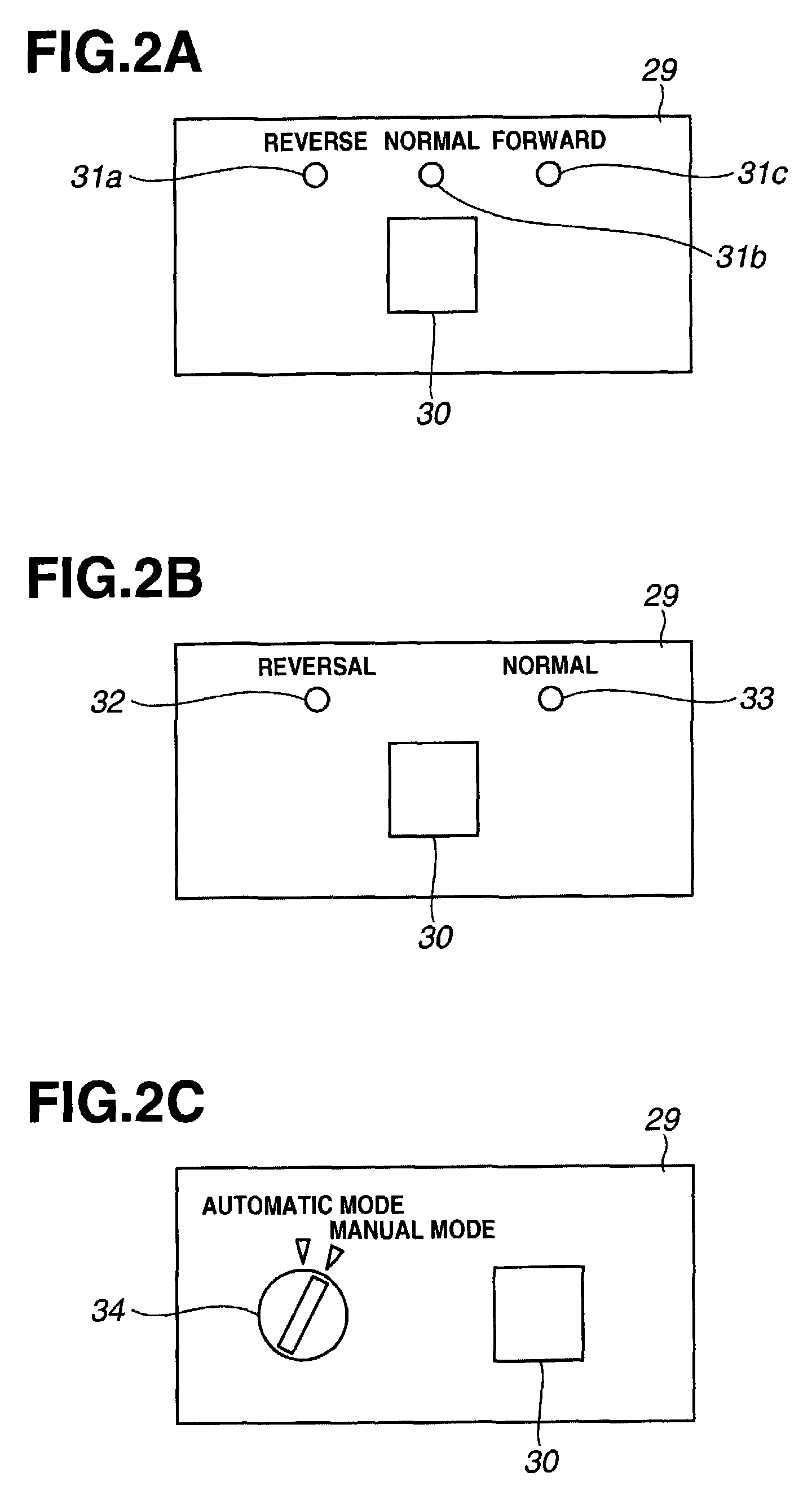
[0150]In the first working example described above, description has been given assuming the case that the reversing switch 30 is constructed as a switch for selecting first reversal processing in which the switching valve 20 is switched from the forward rotation position 20A to the reverse rotation position 20B, and second reversal processing in which the switching valve 20 is switched from the reverse rotation position 20B to the forward rotation position 20A, and the controller 24 implements the first reversal processing upon the reversing switch 30 being operated to select the first reversal processing, and implements the second reversal processing upon the reversing switch 30 being operated to select the second reversal processing. However, as shown in FIG. 2B, implementation is also possible in which the reversing switch 30 is constructed as a switch that instructs reversal processing of switching the switching valve 20 from the forward rotation position 20A to the reverse rota...

third working example

[0158]The lower the oil temperature, the higher the peak pressure becomes, and hence the greater the effect on the durability of the hydraulic equipment, and the greater the effect on the operator.

[0159]Accordingly, in the present working example, the controller 24 carries out control such that the lower the oil temperature value Th, the more the rotational speed N of the hydraulically driven cooling fan 13 is reduced at the times when the switch position of the switching valve 20 is reversed (t3 and t8 in part (a) of FIG. 4), whereby the fan rotational speed N is reduced to the minimum required, so that the peak pressure is reduced reliably.

[0160]Control must thus be carried out such that the lower the oil temperature Th, the lower the fan rotational speed N at each reversal implementation time (t3 and t8 in part (a) of FIG. 4).

[0161]For example, in the case that the oil temperature is a high value Th1, the fan rotational speed required to reduce the peak pressure is a high value N...


PUM


Abstract

An invention relating to a control apparatus and a control method for a hydraulically driven cooling fan for reducing the peak pressure produced upon reversing the switch position of a switching valve, without stopping an engine, and without greatly modifying existing hydraulic circuitry or increasing the apparatus cost. In the invention, in the case that a reversing switch has been operated so as to output a reversal processing commencement instruction signal, control is carried out such that, under the condition that the rotational speed of the engine has decreased to not more than a stipulated rotational speed, capacity adjusting means is controlled, so as to reduce the capacity of a hydraulic pump, and thus reduce the fan rotational speed, and then the switch position of the switching valve is reversed.

Description

[0001]This application claims priority of PCT / JP2006 / 314004 filed Jul. 6, 2006, which is based on Japanese Patent Application Number 2005-197936 filed on Jul. 6, 2005.TECHNICAL FIELD[0002]The present invention relates to a control apparatus and a control method for a hydraulically driven cooling fan, and in particular relates to an apparatus and a method for controlling the switching of the direction of rotation of a hydraulically driven cooling fan.BACKGROUND ART[0003]Engines of construction machinery such as bulldozers and hydraulic excavators are cooled by circulating cooling water (a coolant), heat produced by the engine being dissipated when the cooling water passes through a radiator. With construction machinery, unlike with an automobile or the like, there is little opportunity for an air current caused by traveling to strike the radiator, and hence it is necessary to constantly rotate a hydraulically driven cooling fan in a forward rotational direction, thus creating an air ...

Claims


Application Information

Patent Timeline
Patent Type & Authority Patents(United States)
IPC IPC(8): F01P7/10
CPCF01P5/043F01P7/044
Inventor KAMADO, MITSUHIKOYAMAMOTO, SHIGERUNAKAGAWA, TOMOHIRO
Owner KOMATSU LTD
Why Eureka
Try Eureka