Frequency conversion correction circuit for electrophoretic displays

a technology of frequency conversion and electrophoretic display, applied in the field of frequency conversion correction circuit for electrophoretic display, can solve the problems of color variation or display error, and the cost of additional memory is increased, and achieves the effect of increasing cos

Active Publication Date: 2010-12-28
YUANHAN MATERIALS INC
View PDF2 Cites 124 Cited by
  • Summary
  • Abstract
  • Description
  • Claims
  • Application Information

AI Technical Summary

Benefits of technology

[0005]In view of the conventional EPD has abnormal display problems in extreme environments and a higher cost on the improved techniques, the primary object of the present invention is to provide a control circuit to adjust operation frequency according to operation environments without an additional memory to store look up tables.

Problems solved by technology

But the conventional control circuit usually does not change the driving voltage or applied voltage difference time with temperature alterations during operation, as a result in extreme operation conditions the problem of color variation or display error occurs.
The additional memory also increases the cost.

Method used


Image

  • Frequency conversion correction circuit for electrophoretic displays
  • Frequency conversion correction circuit for electrophoretic displays
  • Frequency conversion correction circuit for electrophoretic displays

Examples


Embodiment Construction

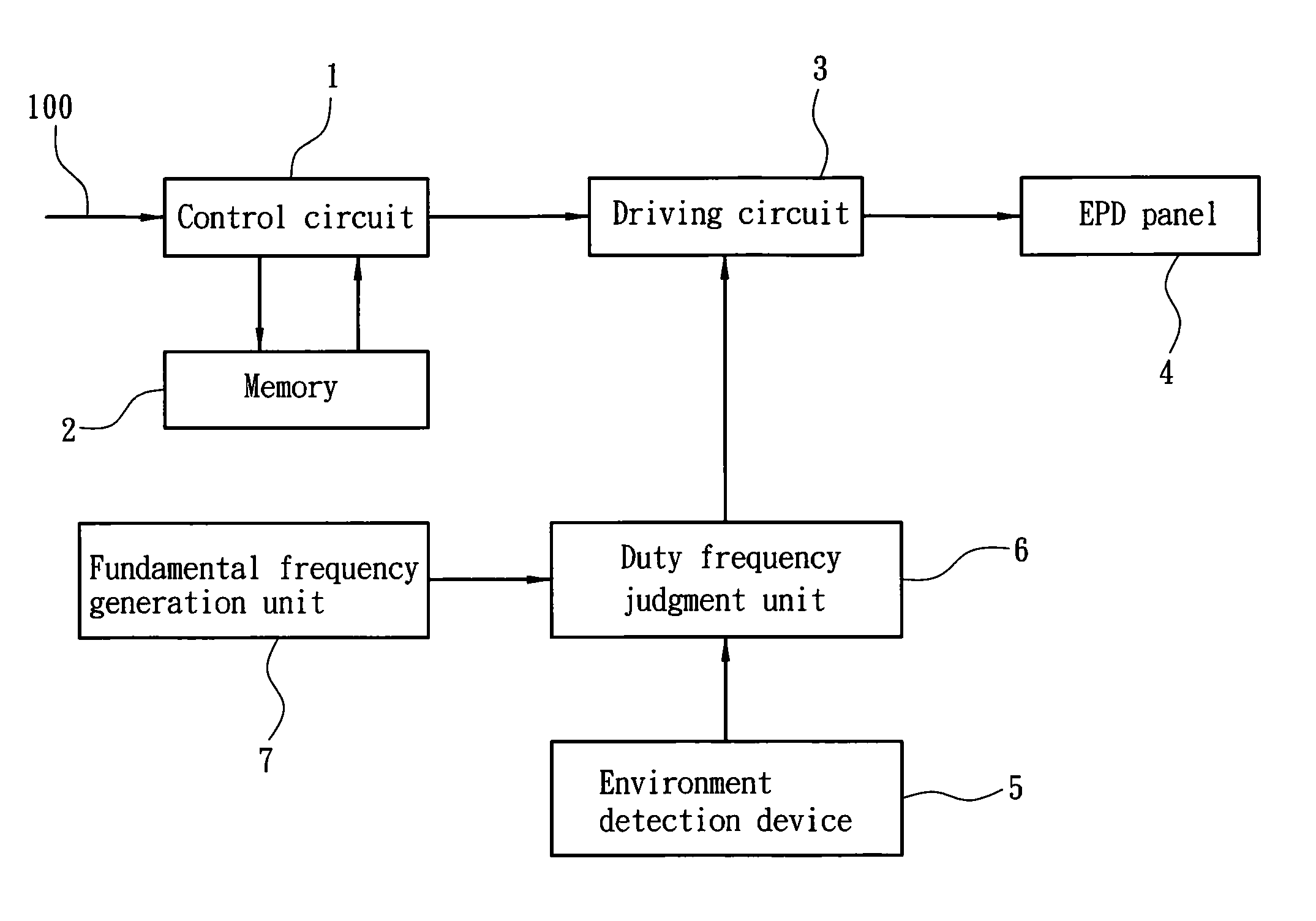
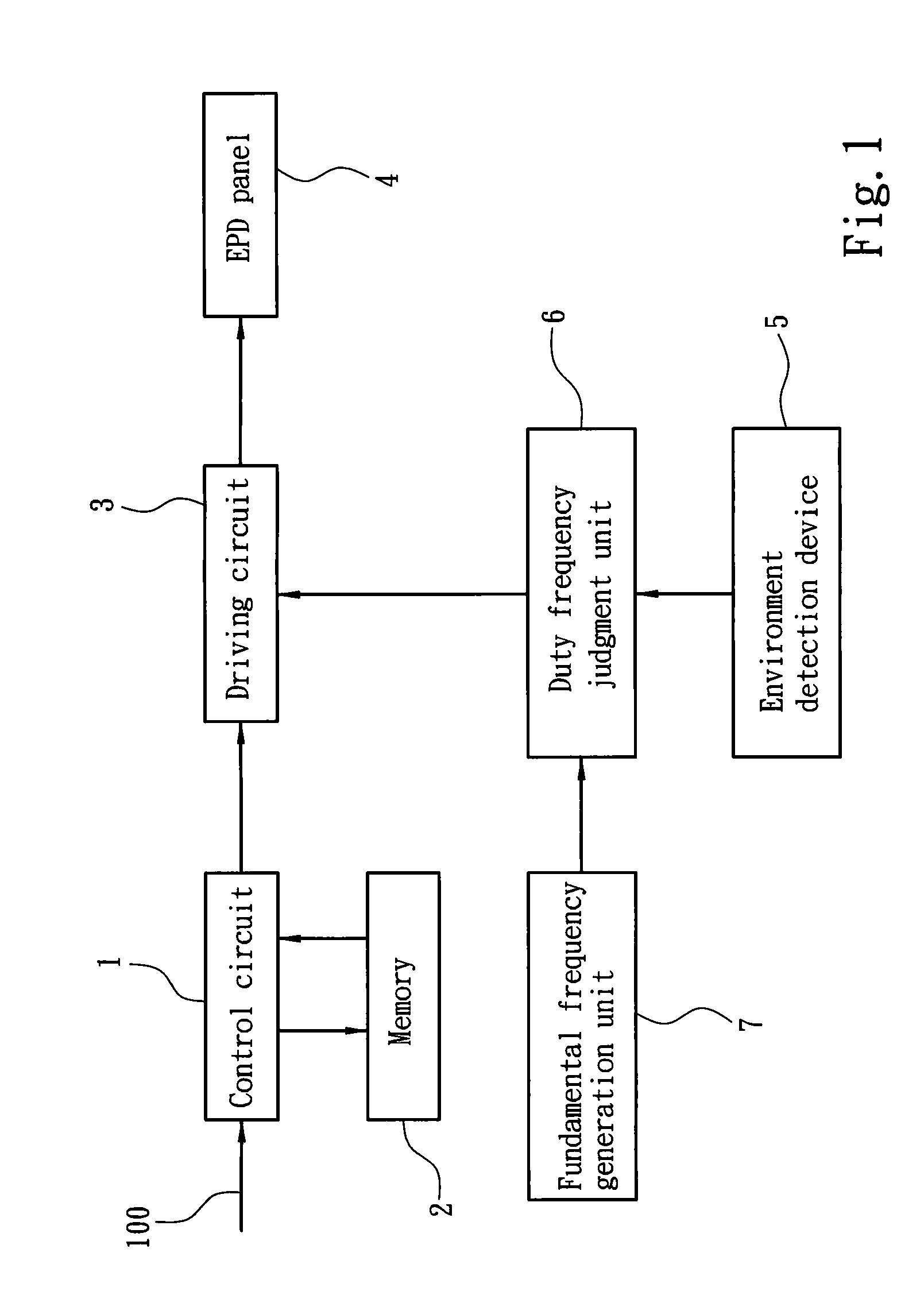
[0011]The present invention aims to provide a frequency conversion correction circuit for an electrophoretic display (EPD). Please refer to FIG. 1, the EPD has a control circuit 1 to capture pixel signals of a next picture. Next, the control circuit 1 gets a corresponding update signal for comparing a pixel to be updated from a look up table in a memory 2, and the update signal is output to a driving circuit 3. The driving circuit 3 provides a plurality set of potential difference signals corresponding to a plurality set of electrodes (not shown in the drawings) of an EPD panel 4 according to the update signal to drive a plurality of charged colored particles in multiple micro cups on the EPD panel 4 to move to display correct colors. Each elapse time for the driving circuit 4 to output the potential difference signals is a fixed frame time. The time series of the potential difference signals output from the driving circuit 3 are affected by duty frequency. The frequency conversion ...


PUM


Abstract

A frequency conversion correction circuit for an electrophoretic display (EPD) which has a control circuit to capture pixel signals of a next picture and gets a corresponding update signal from a look up table to be output, and a driving circuit to provide a plurality set of potential difference signals corresponding to a plurality set of electrodes of an EPD panel according to the update signal. The EPD further has an environment detection device and a duty frequency judgment unit. The environment detection device detects the operation environments of the EPD and gets an environment parameter. The duty frequency judgment unit compares the preset signal value sections where the environment parameter is located and generates a duty frequency signal and sends to the driving circuit. The driving circuit changes and outputs the frequency of the potential difference signals in a fixed frame time according to the duty frequency signal.

Description

FIELD OF THE INVENTION[0001]The present invention relates to a frequency conversion correction circuit for an electrophoretic display (EPD) and particularly to a driving method to adjust and control an EPD through a frequency conversion technique when temperature changes to ensure a display condition is accurate.BACKGROUND OF THE INVENTION[0002]EPD (or called E-paper, E-ink) adopts a display technique different from the conventional displays such as a cathode ray tube (CRT) and liquid crystal display (LCD). An EPD has multiple micro cups in a substrate that contain a colored dielectric solvent and a plurality of charged colored particles suspended in the colored dielectric solvent. There are two electrodes on outer sides of the micro cups. Through the two electrodes, the potential difference at the edges of the micro cups can be changed and the charged colored particles are attracted by magnetic forces and moved to an electrode of an opposite polarity. The movement of the charged co...

Claims


Application Information

Patent Timeline
Patent Type & Authority Patents(United States)
IPC IPC(8): G02B26/00G09G3/34G09G5/00
CPCG09G3/344G09G2310/06G09G2320/0285G09G2320/041G09G2340/16
Inventor CHIU, WEN-PINCHENG, PING-YUEHLIN, FENG-SHOULIN, CRAIGCHAN, BRYAN
Owner YUANHAN MATERIALS INC
Why Eureka
Try Eureka