Ceiling attachment for full-height panel

a full-height panel and ceiling technology, applied in the direction of walls, building roofs, building repairs, etc., can solve the problems of greater difficulty in installing and secureing upright prefabricated panels, particularly ceilings, structural and installation complexities,

Inactive Publication Date: 2011-01-04
HAWORTH SPA
View PDF26 Cites 34 Cited by
  • Summary
  • Abstract
  • Description
  • Claims
  • Application Information

AI Technical Summary

Problems solved by technology

Walls employing full height prefabricated wall panels, however, present greater difficulty with respect to installation and securement of the upright prefabricated panels, particularly with respect to the ceiling.
The attachment structure associated with the upright wall panel, and its cooperation with a track structure attached to the ceiling, however, has often created structural and installation complexities.
This installation process can be difficult to carry out, and more significantly is considered undesirable due to the necessity of creating localized upward lifting of the drop ceiling.
These arrangements, however, are generally difficult to install in that they require one or more installers to effect manual release or movement of the sliding plate or arms, which are typically provided adjacent opposite upper corners of the panel, in order to permit engagement with the ceiling track adjacent opposite upper corners of the panel.
The trim strips, however, cannot both be attached prior to the panel being pivoted upwardly into its upright position since they interfere with access to the attachment structure.
This further complicates the installation of the wall system.
While these constructions do permit the header to be raised and lowered so as to perform the desired function, nevertheless these constructions unnecessarily and undesirably complicate the overall structure of the panel.
In addition, access to the struts during installation of the panel, particularly since such panels must also be joined edge-to-edge during the installation process, is made more difficult.
Some of these arrangements attempt to simplify the problem of accessing the struts by utilizing springs which urge the header upwardly, but this itself creates additional problems with respect to release of the springs and upward urging of the header only when the panel is disposed in precise alignment below the ceiling track.
These general arrangements hence have failed to provide desired structural and operational simplicity coupled with minimization of manufacturing costs.

Method used


Image

  • Ceiling attachment for full-height panel
  • Ceiling attachment for full-height panel
  • Ceiling attachment for full-height panel

Examples


Embodiment Construction

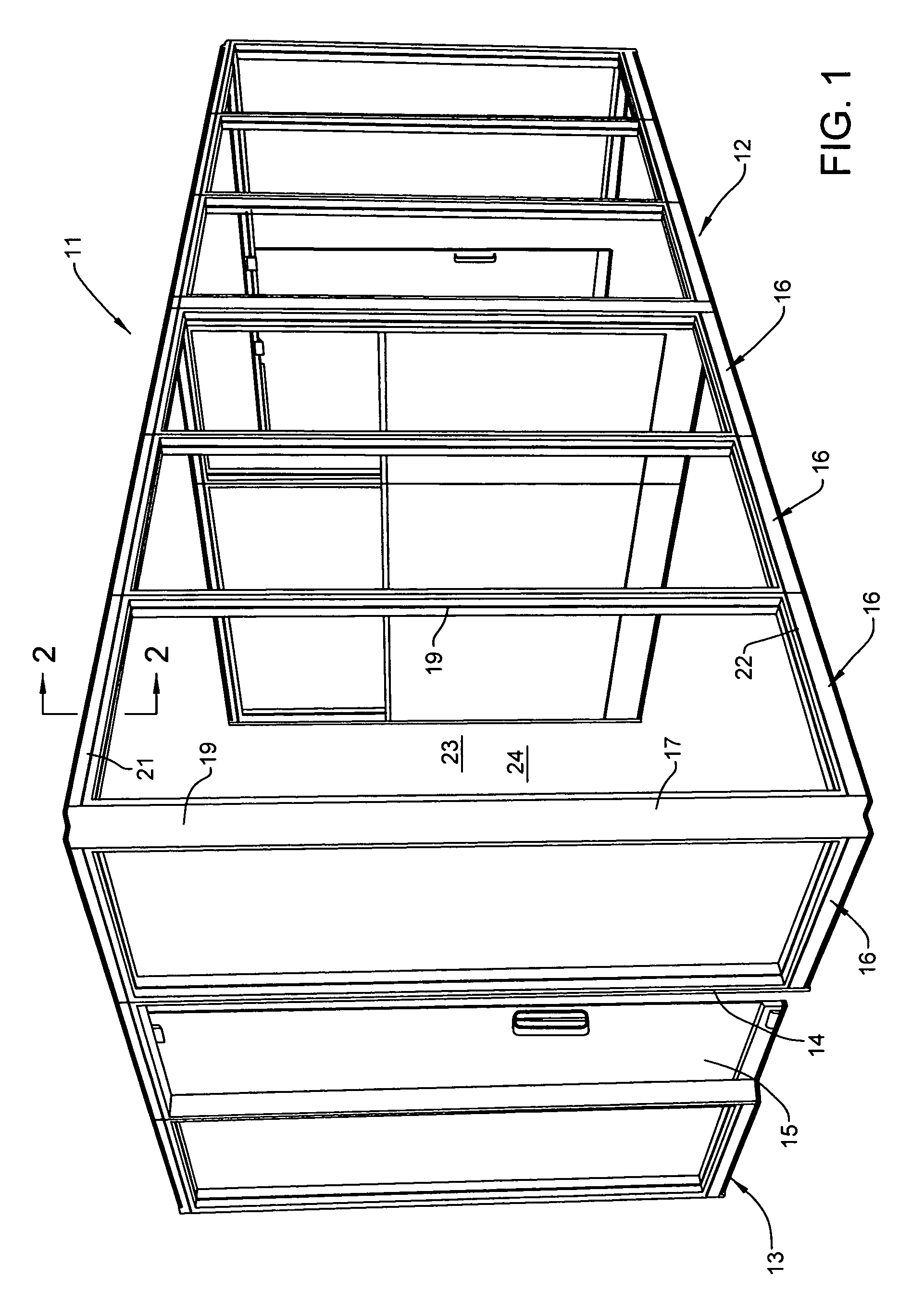
[0026]Referring to FIG. 1, there is illustrated a prefabricated upright wall system 11 intended for support on a floor within a building, and which may cooperate with additional fixed or prefabricated movable walls to assist in dividing a large open area into smaller areas used for offices and the like. The upright wall system 11 may include a plurality of walls which interconnect in angled relationship, such as the walls 12 and 13 illustrated in FIG. 1, and may also include a doorway 14 having a sliding door arrangement 15 associated therewith.

[0027]A wall constructed in accordance with the present invention is typically formed by a plurality of prefabricated upright wall panels 16 which can be joined edge-to-edge in either aligned or angled relationship, with the connection between the edges of adjacent panels being accomplished using any one of many known conventional techniques. The prefabricated wall panels 16, in the illustrated arrangement, are intended to be “full height” pa...


PUM


Abstract

A prefabricated wall panel has a top frame structure defining an upward-opening channel extending lengthwise along the upper edge of the panel. An elongate header member is normally disposed within this channel. The header member is vertically slidably supported on supports fixed to the top frame structure so that the header member, in a storage position, is retained in the space. When the panel has been swung upwardly so that the upper edge is aligned below a preinstalled ceiling track, then the header member is manually displaced upwardly until the header telescopes over the ceiling track. A fixed connection is then formed between the header and the ceiling track to provide lateral stability at the upper edge of the wall panel.

Description

FIELD OF THE INVENTION[0001]This invention relates to an improved header arrangement which cooperates between a ceiling and an upper edge of a prefabricated upright wall panel for permitting securement of the wall panel in an upright position relative to a floor.BACKGROUND OF THE INVENTION[0002]It is conventional practice to subdivide large open areas into smaller work spaces or offices by erecting upright walls constructed from a plurality of prefabricated upright wall panels which are horizontally serially joined in aligned or angled relationship to define the desired wall structure. While the prefabricated wall panels are sometimes of short height so as to project upwardly from the floor through significantly less than floor-to-ceiling height, nevertheless in many instances the need is to define work spaces or offices which provide greater privacy, or closure along hallways and the like, thereby requiring prefabricated wall panels which are of floor-to-ceiling height. Walls emplo...

Claims


Application Information

Patent Timeline
Patent Type & Authority Patents(United States)
IPC IPC(8): E04B2/74E04B2/00
CPCE04B2/7448
Inventor HOULE, ALAIN LEOROY, CHARINE ELLAMCILVENNA, STEVEN CHARLES
Owner HAWORTH SPA
Why Eureka
Try Eureka