Implement transport

a technology of implements and transport positions, applied in soil-working methods, adjusting devices, agricultural tools and machines, etc., can solve the problems of limiting travel, affecting the effect of transport position, and height that is significant,

Inactive Publication Date: 2011-01-04
DILLON PETER
View PDF18 Cites 25 Cited by
  • Summary
  • Abstract
  • Description
  • Claims
  • Application Information

AI Technical Summary

Benefits of technology

[0009]Thus the implement apparatus and method of the present invention provide a convenient and economical transport system for wide implements where the wing frames on which the working members, such as packers, seeding assemblies, land rollers, and the like, are located ahead of a lateral pivot axis such that the wing frames move upward and rearward, and then fold back behind the hitch to the transport position. Thus in the transport position the working members are located toward the outside of the parallel rear trailing wing frames, instead of between the wing frames as in the prior art. Thus the working members are not subject to touching each other during transport, reducing the risk of damage.

Problems solved by technology

A significant issue with wider implement is that they must be converted into a narrower transport position in order to move along relatively narrow roads from one field to another.
As these implement grow wider it becomes more problematic to design an implement with wings that will fold to a width that allows for efficient transport.
In addition, when folding the wings upward as in the machine illustrated in U.S. Pat. No. 6,684,962 to Lewallen results in a transport position that has a significant height, and which may exceed limits on some roads and restrict travel.

Method used


Image

  • Implement transport
  • Implement transport
  • Implement transport

Examples


Embodiment Construction

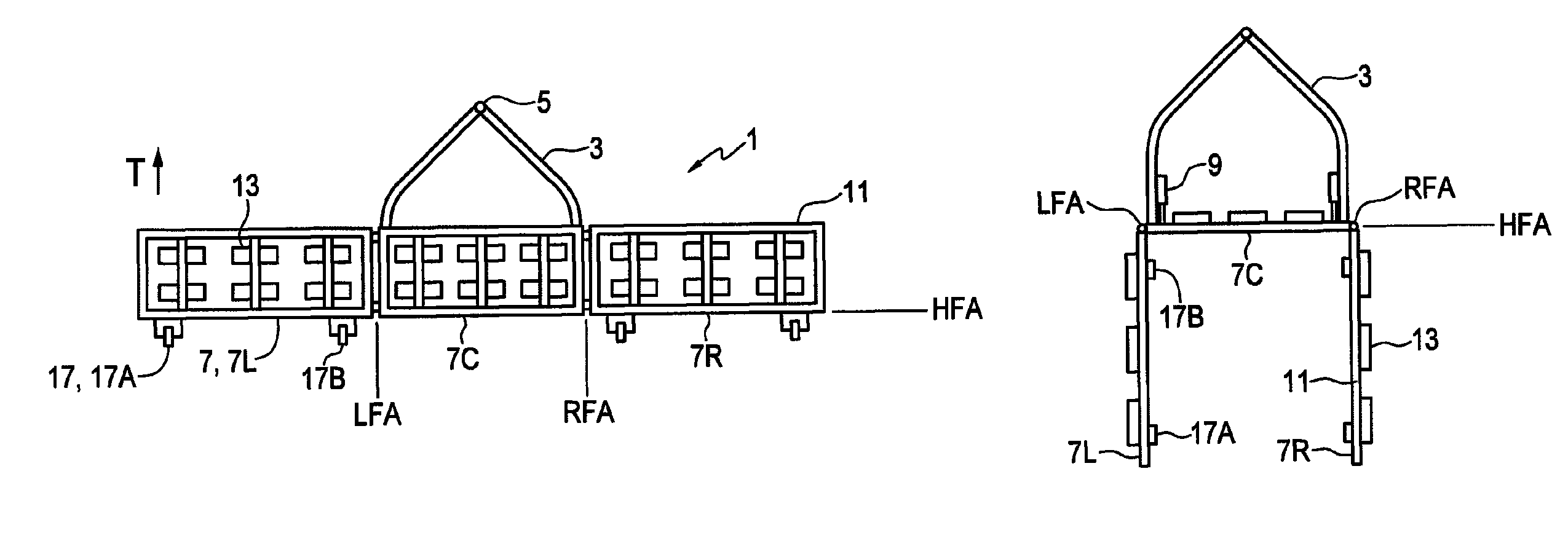
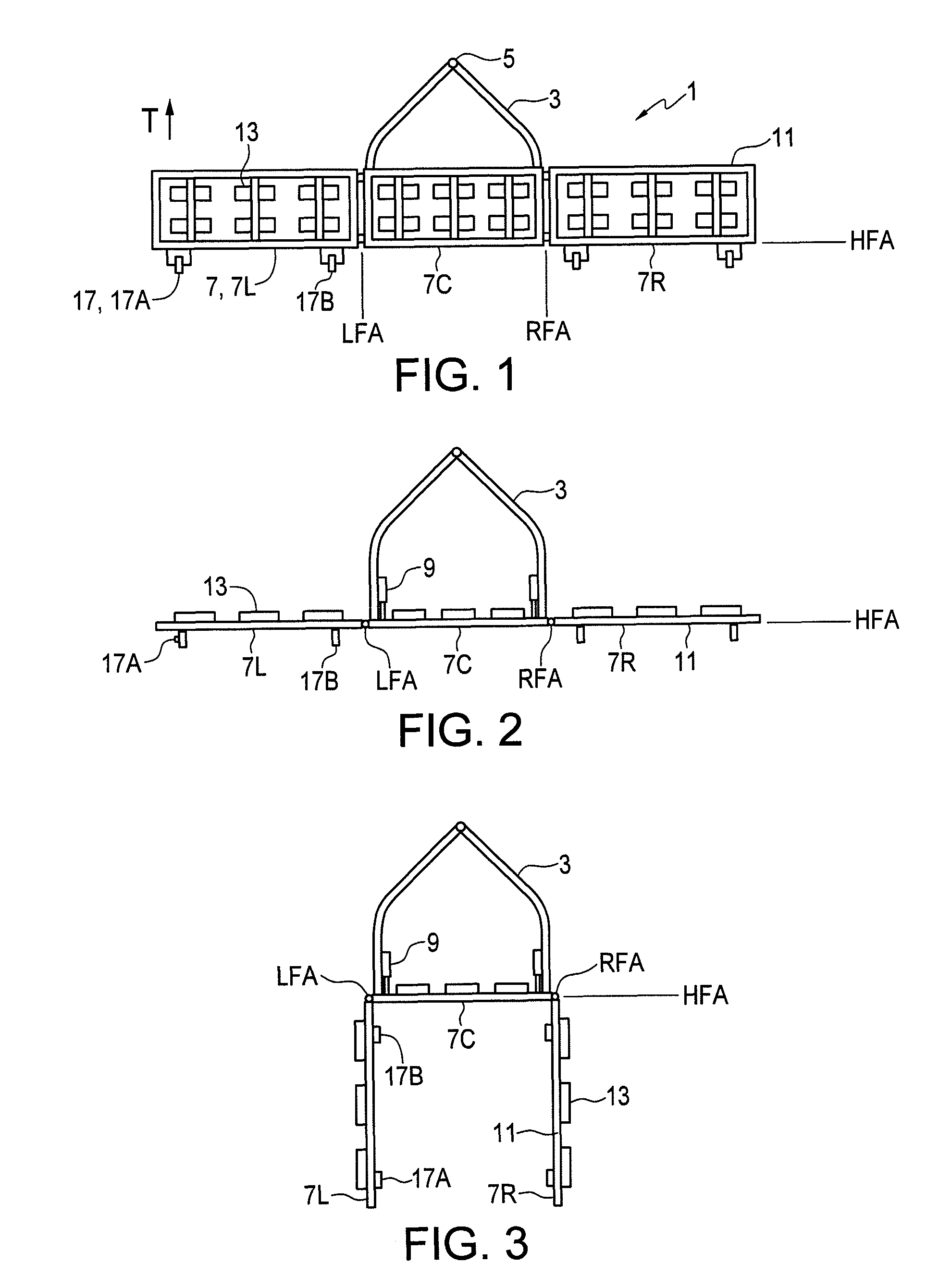
[0030]FIGS. 1-3 and 7-9 schematically illustrate an embodiment of an implement apparatus 1 of the present invention. The apparatus 1 is adapted for attachment to a towing vehicle for movement in an operating travel direction T. The apparatus 1 comprises a hitch frame 3 with a hitch 5 at a front end thereof adapted for attachment to the towing vehicle. A center frame section 7C is pivotally attached to a rear portion of the hitch frame 3 about a substantially horizontal hitch frame axis HFA oriented substantially perpendicular to the operating travel direction T. A right wing frame section 7R is pivotally attached to a right end of the center frame section 7C about a right frame axis RFA, and a left wing frame section 7L is pivotally attached to a left end of the center frame section 7C about a left frame axis LFA oriented substantially parallel to the right frame axis RFA.

[0031]A pair of lift actuators 9 is operative to pivot the center frame section 7C upward about the hitch frame ...


PUM


Abstract

An implement apparatus includes a hitch frame, center frame section, and right and left wing sections pivotally attached to the center section. An actuator pivots the center frame section upward about the hitch frame axis at the rear of the hitch frame to raise the frame sections upward and rearward from a horizontal aligned operating position, where front ends of the frame sections are forward of the hitch frame axis, to a raised position where the frame sections are oriented vertically. Working members mounted to the frame sections forward of the hitch frame support the apparatus on the ground in the operating position, move upward off the ground in the raised position. Transport wheels rearward of the hitch frame axis are above the ground in the operating position, and move down to support the apparatus in the raised position, where wing sections can pivot rearward to the transport position.

Description

[0001]This invention is in the field of agricultural implements and in particular a transport system for such implements.BACKGROUND[0002]Wide agricultural implements are popular in more open agricultural areas where fields are large. With an implement making a wide swath, fewer the passes are required than with a narrower implement, and generally the operation can be completed in less time. A significant issue with wider implement is that they must be converted into a narrower transport position in order to move along relatively narrow roads from one field to another.[0003]Wide implements generally comprise laterally extending wings that fold for transport in a variety of different ways. U.S. Pat. No. 6,684,962 to Lewallen illustrates an implement where the wings fold upward about a number of pivot axes oriented parallel to the operating travel direction of the implement. In U.S. Pat. No. 3,654,999 to Fischer the implement wings pivot rearward about a vertical pivot axis.[0004]In U....

Claims


Application Information

Patent Timeline
Patent Type & Authority Patents(United States)
IPC IPC(8): A01B63/00
CPCA01B73/02
Inventor DILLON, PETER
Owner DILLON PETER
Why Eureka
Try Eureka