Air removal unit

a technology of air removal unit and air filter, which is applied in the direction of cooling/ventilation/heating modification, electrical apparatus casing/cabinet/drawer, electrical apparatus, etc., can solve the problems of heat generation, adverse effects on equipment performance, reliability and useful life, and inability to maintain and service in the field or replace, etc., to achieve high airflow capacity, quick and easy installation, and high airflow capacity

Active Publication Date: 2011-01-04
AMERICA POWER CONVERSION CORP
View PDF105 Cites 92 Cited by
  • Summary
  • Abstract
  • Description
  • Claims
  • Application Information

AI Technical Summary

Benefits of technology

[0013]In addition, the unit also may comprise a blanking panel. The blanking panel is constructed and arranged to removably connect to a bottom portion of the unit and to blank-off an exposed area disposed below the unit when the unit is installed to the equipment rack or enclosure to help to minimize loss of air from the unit, and also to help to minimize flow of air from and into an interior of the equipment rack or enclosure.
[0034]In addition, the air removal unit may be integrated into a cooling air system that includes an air cooler or conditioner and a return air plenum as described above. The return air plenum may receive exhaust air from the air removal unit and supply it to the air cooler or conditioner such that air is cooled or conditioned before it is returned and supplied to an equipment room or data center from which it was vented. The cooling air system in which the air removal unit is incorporated thereby eliminates the need for a double or raised floor configuration and refrigeration equipment to provide chilled or cold air for cooling. In effect, the air removal unit and the cooling air system each essentially avoid the infrastructure requirements and the operating and maintenance costs associated with raised floor configurations, while it provides high flow rates of cooling air.

Problems solved by technology

Rack-mounted communications and information technology equipment, such as servers, CPUs, communications and internetworking equipment, consume electrical power and generate heat during operation.
Without effective thermal management, heat generation can have adverse effects on the performance, reliability and useful life of equipment.
For instance, heat generated from rack-mounted equipment contained within an enclosure can build-up within the confines of the enclosure and create hot spots that electronic components are particularly vulnerable to.
Similarly, without managing the thermal output of equipment racks or enclosures, hot spots and adverse thermal conditions can develop in equipment rooms and data centers, creating inferior operating environments.
Such airflow rates can be affected by a number of conditions and obstructions including static air pressure and other floor tiles.
This floor configuration may be difficult or impossible to provide if the equipment room or data center is crowded and includes multiple high power racks or enclosures, and such racks or enclosures are arranged side-by-side in rows.
In addition, raised floor configurations are relatively inflexible with respect to reconfiguring and rearranging an equipment room or data center to meet changing and new equipment needs.
Such raised floor configurations therefore do not inexpensively accommodate the manner in which equipment components and racks or enclosures are deployed in an equipment room.
Further, raised floor configurations and associated cooling systems are not flexible or portable with respect to different power consumptions between different racks and enclosures and different areas within a given equipment room or data center.
In this case, raised floor configurations cannot easily and cost effectively vary and / or concentrate cooling airflow where needed within the equipment room.
Local thermal problems, such as thermal gradients and hot spots, therefore can result due to insufficient cooling.

Method used


Image

  • Air removal unit
  • Air removal unit
  • Air removal unit

Examples


Embodiment Construction

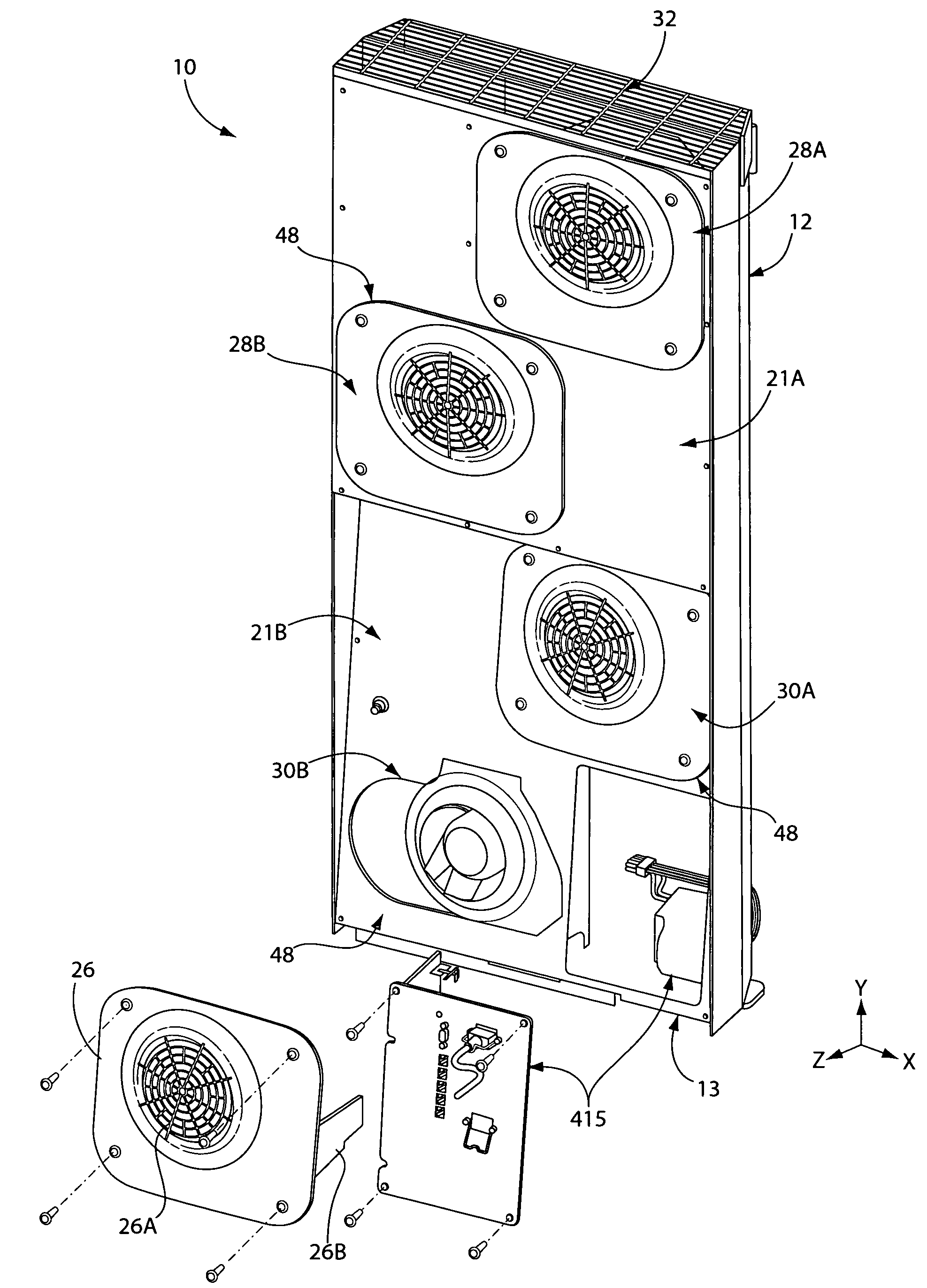
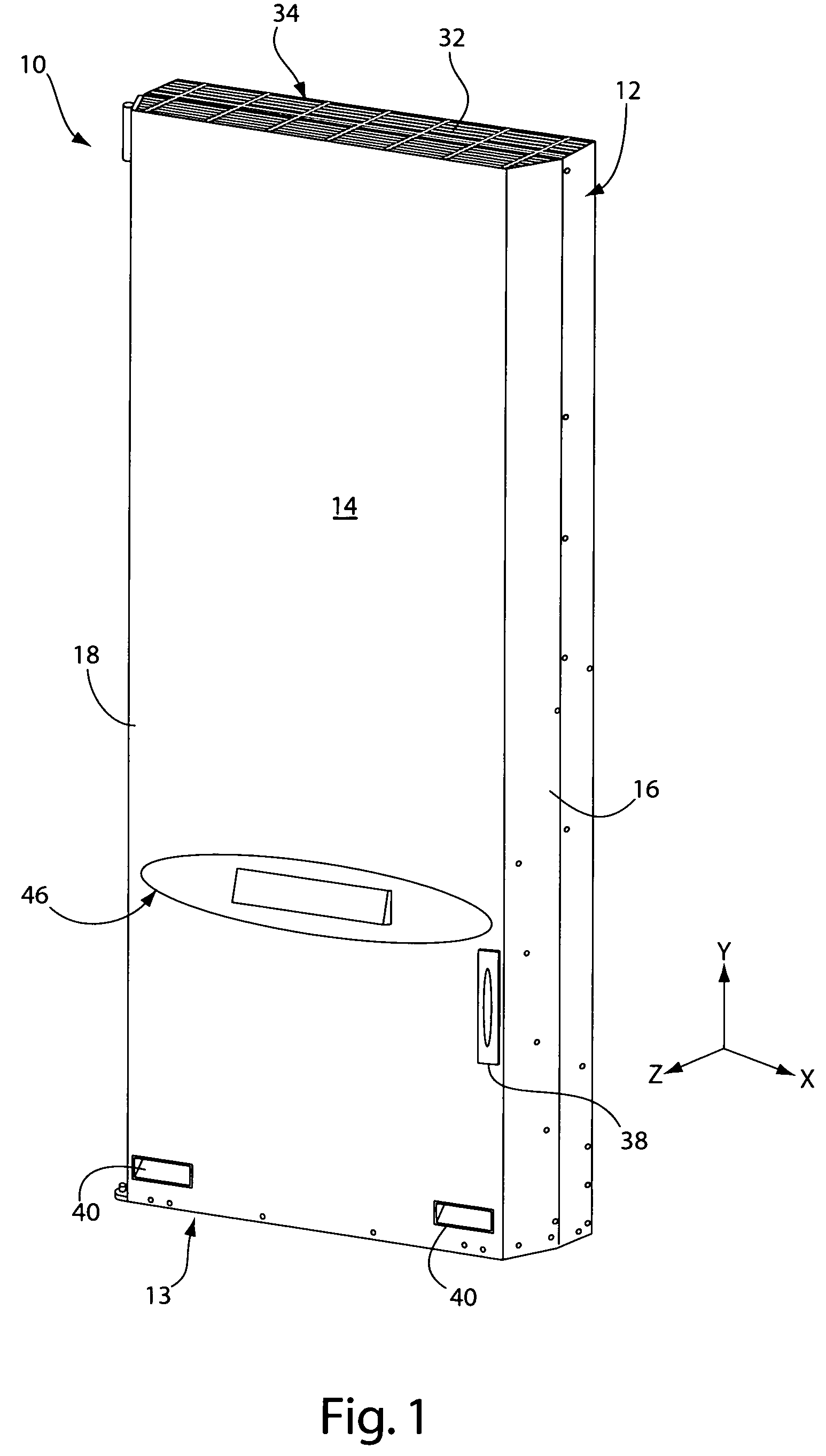
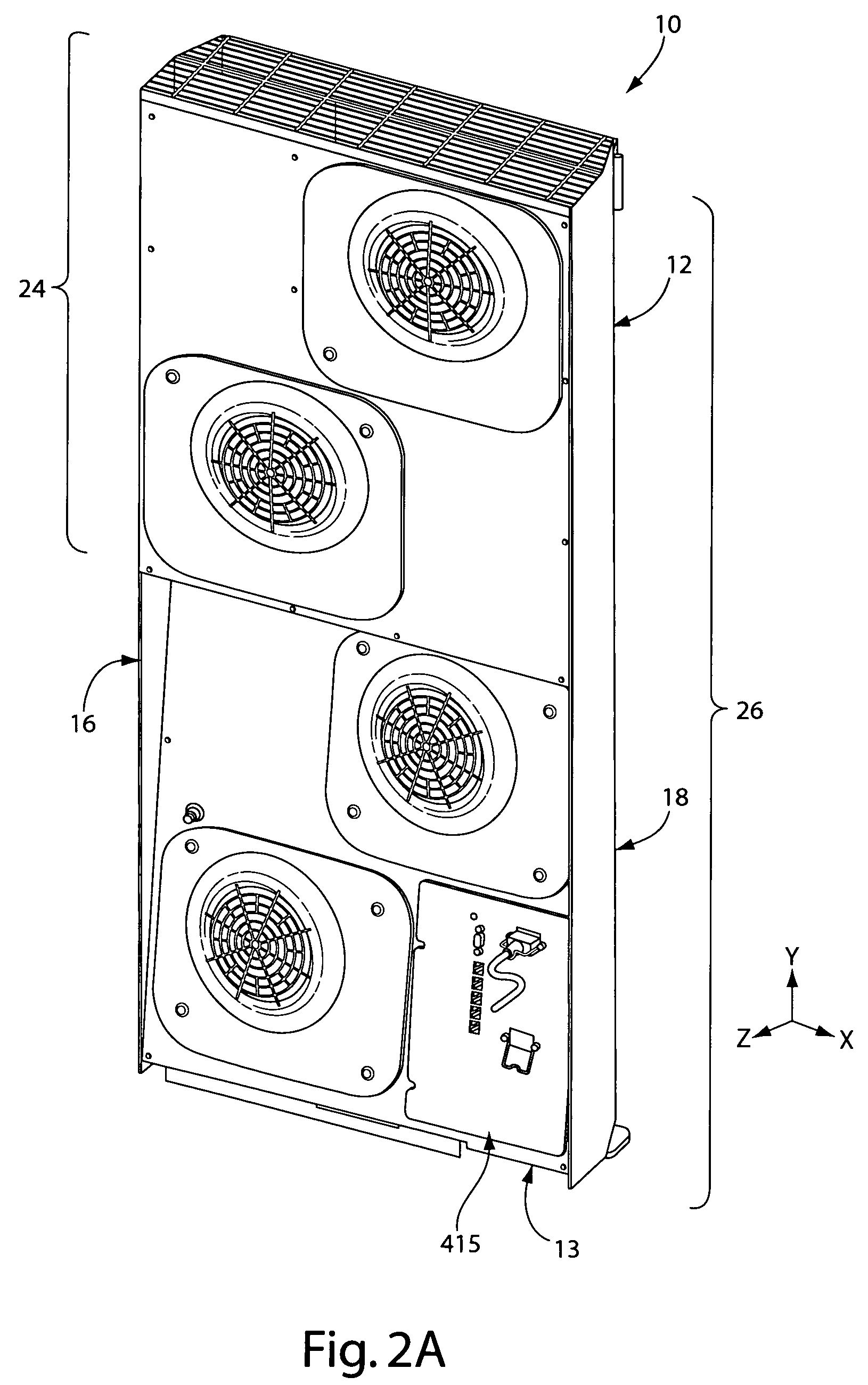
[0061]The invention provides an air removal unit for removing exhaust air from a rack or an enclosure designed to house information, communications and / or other types of electronic equipment. The air removal unit according to the invention is configured to remove exhaust air from an equipment rack or enclosure to help to manage the thermal output of rack-mounted equipment, such as servers, CPUs and other electronics. The unit is constructed and arranged to mount or install directly to an exhaust side of an equipment rack or enclosure and to serve as a moveable panel or door of the rack or enclosure. The configuration and design of the unit thereby enables the unit to install to existing racks or enclosures without significant retrofitting and further permits in-field installation, maintenance, service and replacement of the unit and its components.

[0062]The unit includes an upper and a lower exhaust module contained within a single housing wherein each exhaust module includes two fa...


PUM


Abstract

An air removal unit configured for removing exhaust air from an equipment rack or enclosure includes multiple fans to achieve a high airflow capacity while defining a compact and portable structure. The unit removably installs along an exhaust side of an equipment rack or enclosure to provide capabilities for managing the thermal output of equipment, such as servers, CPUs, communications, internetworking and other types of equipment. The unit includes one or more upper fan modules and one or more lower fan modules positioned below the upper fan modules. The upper and the lower fan modules are arranged in a stacked configuration along the depth of the unit with the lower fan modules positioned in an offset orientation relative to the upper fan modules. The stacked configuration and the offset orientation of the fan modules help to incorporate multiple fans with the unit while maintaining the compact and portable design. The unit is further configured to serve as a door of an equipment rack or enclosure to thereby provide access to the unit and the rack or enclosure during operation. The unit can be incorporated with a ventilation system or a cooling air system associated with an equipment room or data center.

Description

FIELD OF THE INVENTION[0001]The invention relates to an air removal unit for use with an equipment rack or equipment enclosure housing information, communications and / or other types of electronic equipment. The invention also relates to an air cooling system for an equipment room or data center including the air removal unit.BACKGROUND OF THE INVENTION[0002]Rack-mounted communications and information technology equipment, such as servers, CPUs, communications and internetworking equipment, consume electrical power and generate heat during operation. Without effective thermal management, heat generation can have adverse effects on the performance, reliability and useful life of equipment. For instance, heat generated from rack-mounted equipment contained within an enclosure can build-up within the confines of the enclosure and create hot spots that electronic components are particularly vulnerable to. Similarly, without managing the thermal output of equipment racks or enclosures, ho...

Claims


Application Information

Patent Timeline
Patent Type & Authority Patents(United States)
IPC IPC(8): H05K5/00
CPCH05K7/20736H05K7/20
Inventor MCMAHAN, LIANNE M.PERRY, LOURAO, PRASADMCKENNA, BRIAN
Owner AMERICA POWER CONVERSION CORP
Why Eureka
Try Eureka