Portable arm exoskeleton for shoulder rehabilitation

a technology of exoskeleton and portability, which is applied in the field of powered arm exoskeletons, which can solve the problems of exceedingly difficult joint range matching, limited range of motion, and unconstrained human torsos

Active Publication Date: 2011-01-04
CARIGNAN CRAIG R +1
View PDF13 Cites 99 Cited by
  • Summary
  • Abstract
  • Description
  • Claims
  • Application Information

AI Technical Summary

Problems solved by technology

Matching the joint ranges is exceedingly difficult when using single-axis revolute joints because the linkages easily interfere with each other thus limiting the range of motion.
In floor-mounted exoskeletons, the posture of the human torso is left unconstrained, and the exoskeleton configuration with respect to the torso cannot be determined without external instrumentation.
These types of exoskeletons are typically not capable of exerting enough force for exercise therapy or having the interfaces required to apply force at multiple contact points along the length of the arm.
Many kinematic properties required for shoulder therapy, such as anthropomorphic range of motion and torso-to-shoulder articulation, are often lacking as well.
Note that several labs have also built passive (unpowered) exoskeletons for various purposes, but these cannot exert forces required for physical therapy.
It not powerful enough to be used for physical therapy (Johnson, 2001).
In addition, the first shoulder joint axis is parallel to the torso azimuth axis, which produces a singularity when the upper arm is horizontal thereby limiting its usable workspace.
Although this vertical motion is approximately correct, it is not along an arc traveled by the anatomical shoulder joint.
While this design allows full torso-to-shoulder articulation, the prismatic joint and several of the rotational joints in the shoulder complex are passive (spring-loaded) and thus cannot be actively controlled.

Method used


Image

  • Portable arm exoskeleton for shoulder rehabilitation
  • Portable arm exoskeleton for shoulder rehabilitation
  • Portable arm exoskeleton for shoulder rehabilitation

Examples


Embodiment Construction

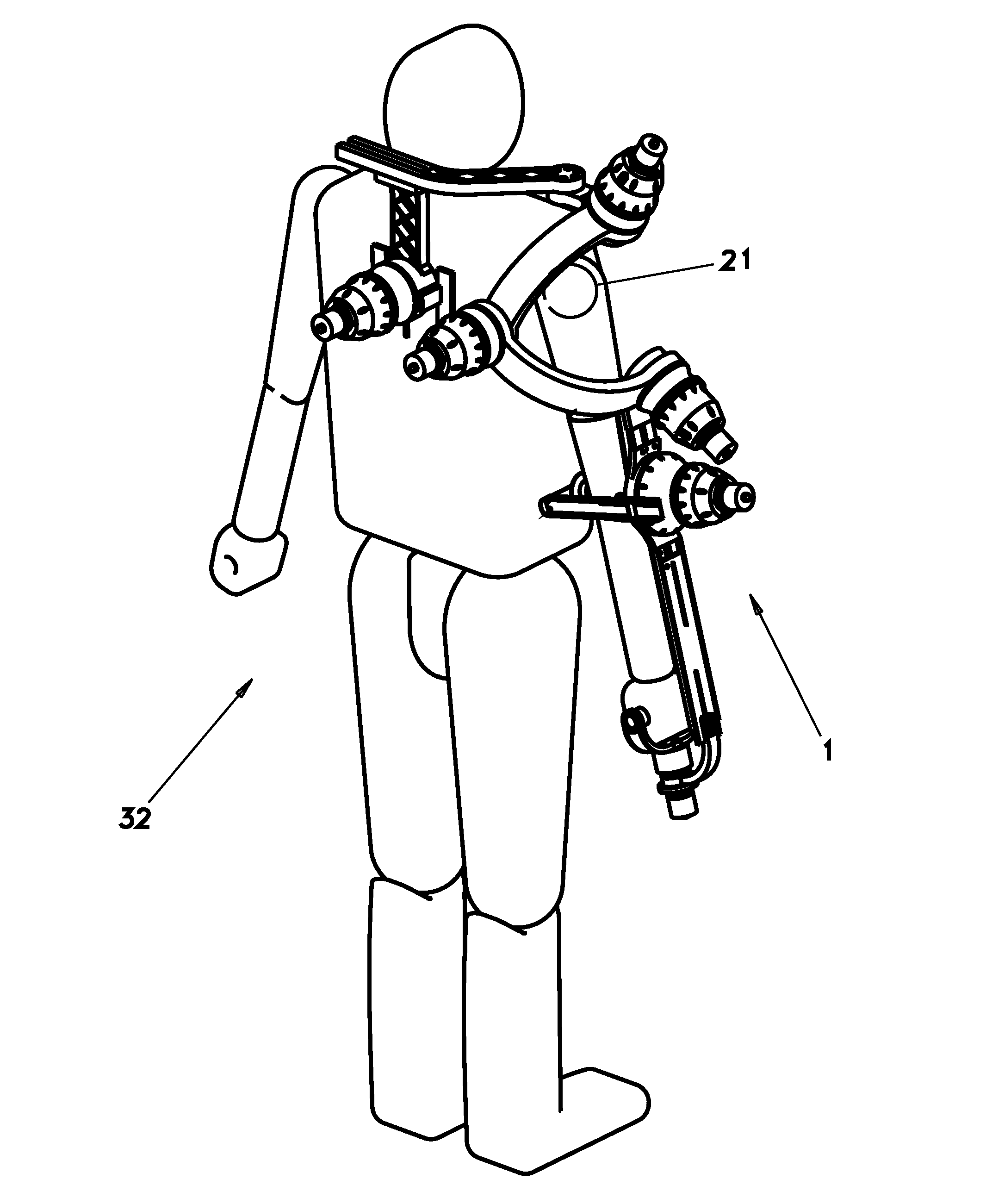
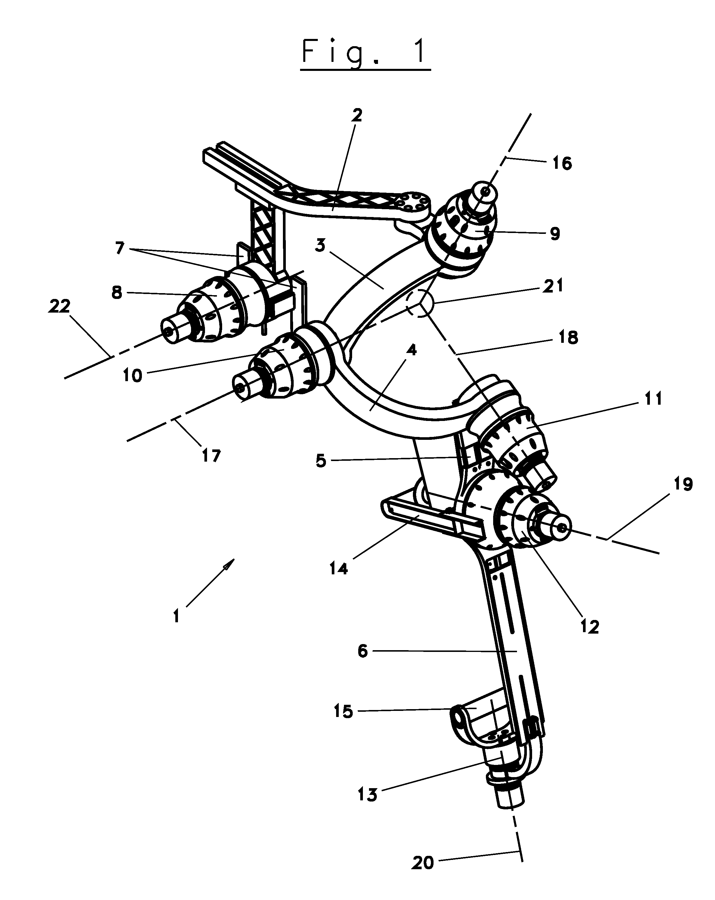
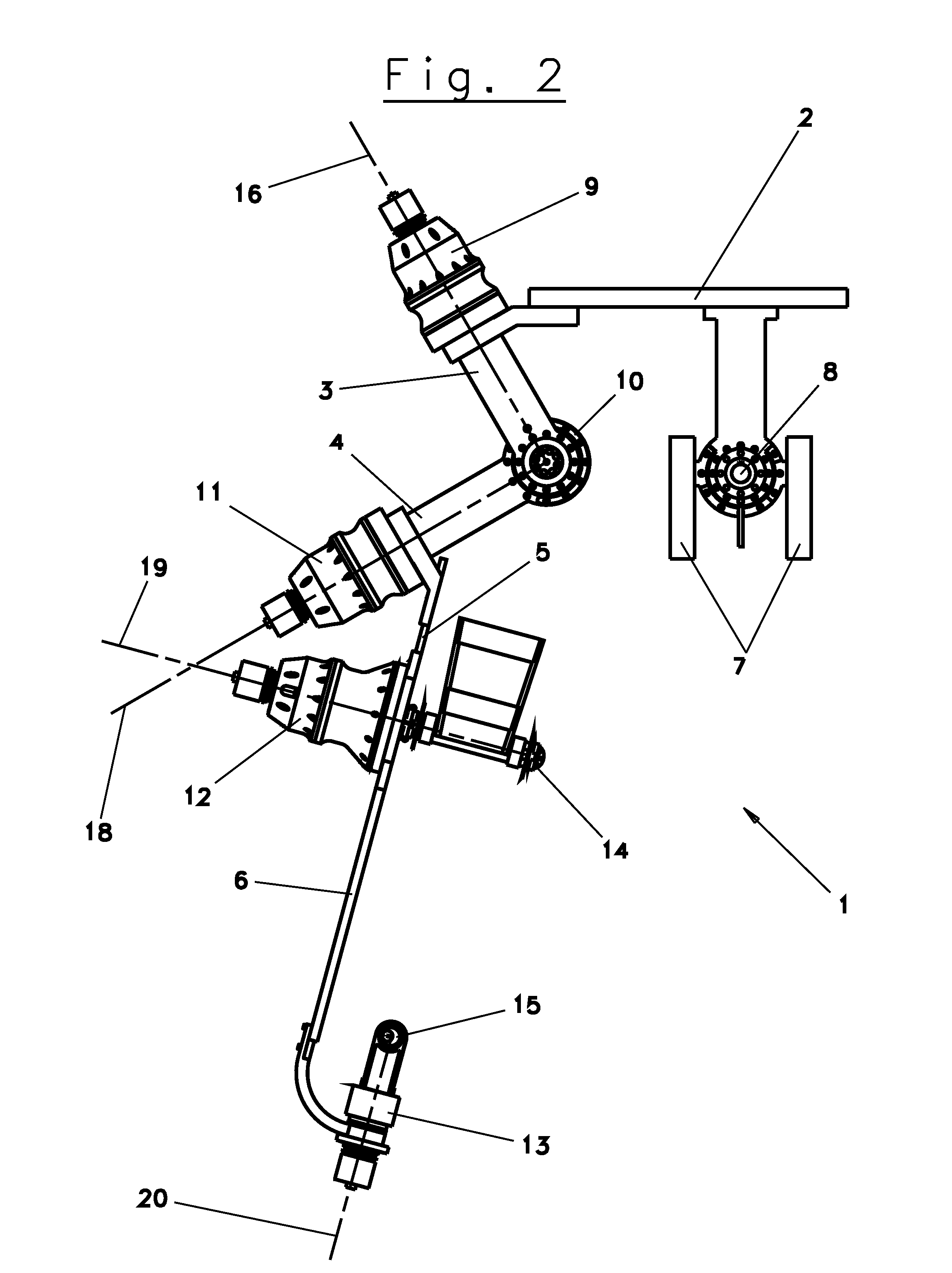
[0056]In FIGS. 1 to 4 a possible embodiment is shown of an exoskeleton interface apparatus 1, according to the invention, for measuring the posture of the scapula, arm, forearm, and wrist of a human and for reflecting controlled forces in predetermined areas of contact thereof.

[0057]As shown in said figures, the apparatus 1 comprises six rigid links 2-7 arranged in series capable of rotating reciprocally at the respective ends for monitoring angular movements of the scapula, arm, forearm, and wrist of a human 32 and having at the tip a handgrip 15 for the human 32 same (FIGS. 10-13) for reflecting a force feedback.

[0058]In particular, rigid links 3 and 4 can rotate at their ends by rotational joints 9-11, which have their rotational axes 16-18 incident in a point 21 that is the intersection of the physiological axes of the shoulder.

[0059]More in detail, exoskeleton 1 comprises a rigid link 7, capable of being mounted on a backpack or vest worn by the human 32 for the purpose of adju...


PUM


Abstract

The present invention relates to an exoskeleton interface apparatus that parallels human arm motion and is comprised of a serial assemblage of five powered linkages and joints based at a rigid support structure worn on the torso of the human subject. Such apparatus generates shoulder rotation using three orthogonal revolute joints mounted on serial linkages encompassing and intersecting at the anatomical glenohumeral joint. Elevation of the shoulder joint is articulated using a link member driven by a single revolute joint mounted in the torso structure. Passive adjustable linkages are used to match variation in anatomical forearm length, upper arm length, and scapula-to-glenohumeral radius. A plurality of integrated dc motor / harmonic drive transmission modules is co-located on adjoining linkages to power the joints. Force is exchanged with the human at the handgrip and elbow brace, and reacted to the torso structure via the base attachment. The present invention is applicable in particular to rehabilitation of the shoulder.

Description

CROSS-REFERENCE TO RELATED APPLICATIONS[0001]This application claims the benefit of U.S. Provisional Application No. 60 / 743,695 filed on Mar. 23, 2006.STATEMENT REGARDING FEDERALLY SPONSORED RESEARCH OR DEVELOPMENT[0002]This research was sponsored by the Department of the Army Medical and Materiel Command under Grant #W81XWH-04-1-0078K (K. Cleary, P. I.; Jan. 1, 2004-Jan. 21, 2008). The U.S. Army has ceded the rights on this invention, but retains a royalty-free, non-exclusive license to use and make the invention or have the invention used or made for governmental purposes.BACKGROUND OF THE INVENTION[0003]1. Field of the Invention[0004]The present invention relates to an electromechanical robotic device that is worn over the human arm.[0005]In particular, this invention relates to a torso-mounted, powered arm exoskeleton that is capable of moving in parallel with the human arm, reacting and exerting forces, and providing sensory feedback during shoulder rehabilitation.[0006]2. Desc...

Claims


Application Information

Patent Timeline
Patent Type & Authority Patents(United States)
IPC IPC(8): A61H1/02
CPCA61H1/0281B25J9/0006B25J17/025A61H2201/165
Inventor CARIGNAN, CRAIG R.LISZKA, MICHAEL SCOTT
Owner CARIGNAN CRAIG R
Why Eureka
Try Eureka