Pattern forming method and pattern forming apparatus

a pattern forming and pattern forming technology, applied in the field of pattern forming methods and pattern forming apparatus, can solve the problems of local difference in amount of resin material, waving, strain, and reduced processing accuracy in some cases

Inactive Publication Date: 2011-01-04
CANON KK
View PDF4 Cites 257 Cited by
  • Summary
  • Abstract
  • Description
  • Claims
  • Application Information

AI Technical Summary

Benefits of technology

[0031](6) A pattern transfer apparatus for transferring a shape of a mold onto a cured resin material on a substrate by filling and curing a liquid curable resin material between the mold and the substrate, wherein the pattern transfer apparatus includes an application position control means for controlling an application position of the liquid curable resin material so as not to cause excess and deficiency of an amount of the resin material depending on filling location when the resin material is filled between the mold and the substrate.
[0038]According to the present invention, during the imprint operation, it is possible to effect control for uniformizing the amount of the resin material interposed between the mold and the substrate.

Problems solved by technology

For example, excess and deficiency of a resin material can be caused depending on location by evaporation of a liquid curable resin material, a shape of a mold, a strain of a substrate, or the like when the resin material is filled between the mold and the substrate, thus resulting in a decreased processing accuracy in some cases.
Further, in many cases, the mold causes waving, strain, etc.
Further, when resin material droplets are applied, a difference in amount of the resin material can be locally caused by evaporation of the resin material.
In such very small amounts of the resin material, due to the above described mold shape, substrate strain, resin material evaporation, or the like, there occurs locally insufficient filling of the resin material or an unacceptable irregularity in thickness of the resin material layer in some cases.
However, by this method, it is essentially difficult to continuously and precisely control a very small amount of liquid.
Further, the method is accompanied with such a problem that an error in amount of the liquid or an increase in cost due to condition setting for precise temperature control for preventing the resin material amount error.

Method used


Image

  • Pattern forming method and pattern forming apparatus
  • Pattern forming method and pattern forming apparatus
  • Pattern forming method and pattern forming apparatus

Examples


first embodiment

[0046]A pattern forming method, according to this embodiment, for forming a pattern on a pattern forming material on a substrate by using an imprint pattern provided to a mold has the following features.

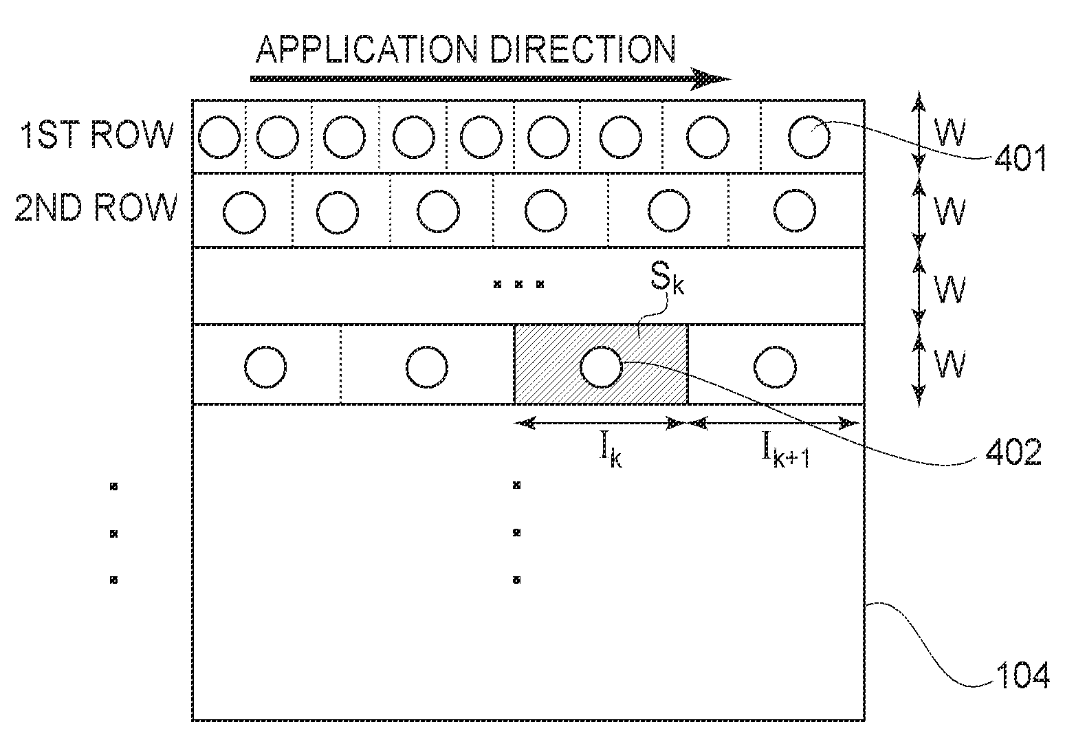
[0047]First, a substrate having thereon a pattern forming area is prepared and in the pattern forming area, a pattern forming material placed in an uncured state is disposed in a dispersion state at a plurality of positions at different intervals. As the pattern forming material, a photocurable resin material or a thermosetting resin material can be used.

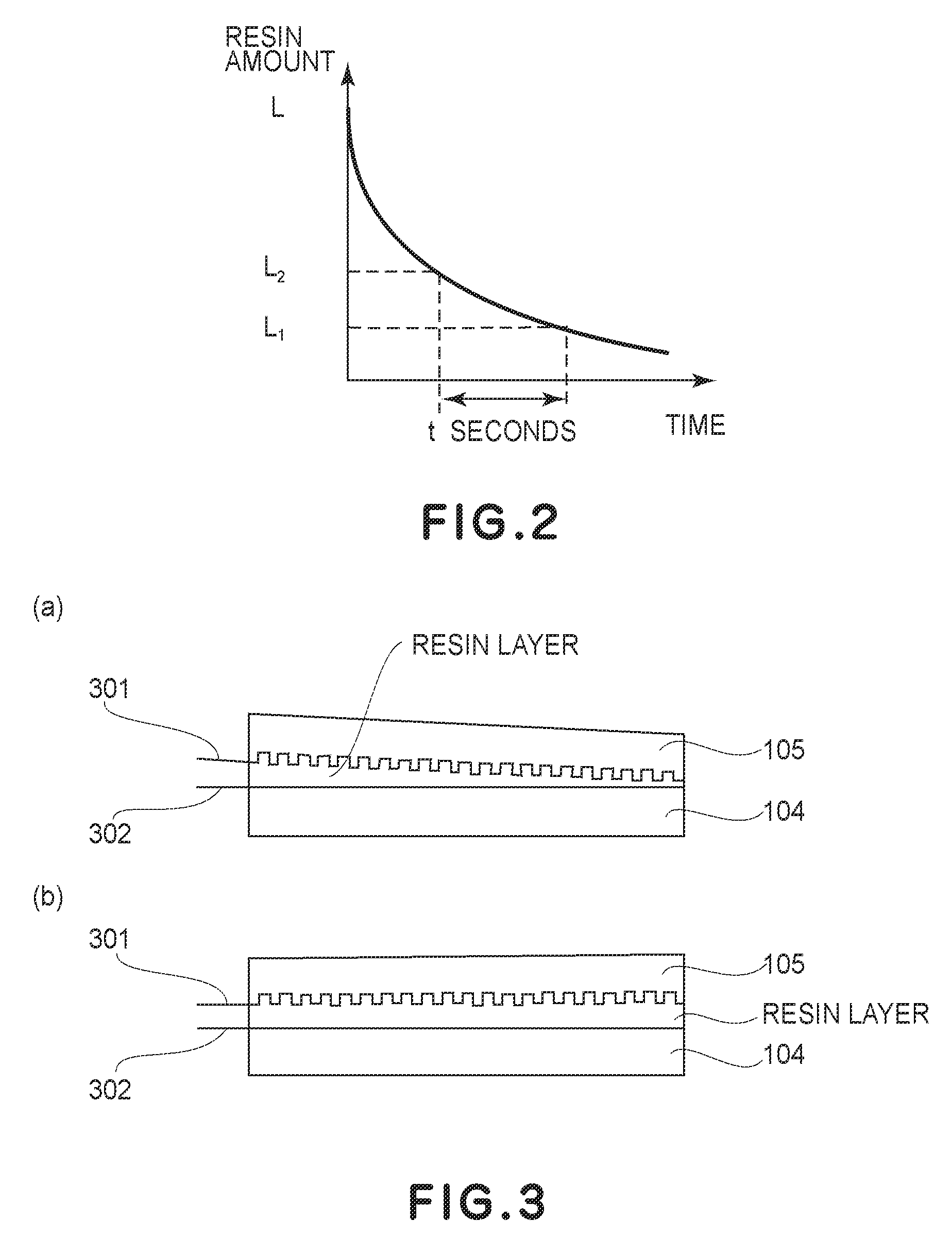
[0048]Thereafter, the mold and the substrate are disposed opposite to each other so as to be placed in a state in which the pattern forming material is interposed between the mold and the substrate. Then a gap between the mold and the substrate is gradually decreased, so that the pattern forming material is deformed in a shape corresponding to a shape of the imprint pattern provided to the mold and is then cured. In order to cure the...

second embodiment

[0061]A pattern forming apparatus according to this embodiment is an apparatus for effecting pattern formation by the pattern forming method according to First Embodiment. Specifically, the pattern forming apparatus includes a mold holding portion for holding the mold described above, a substrate holding portion for holding the substrate described above, and an application portion for applying the above described pattern forming material on the substrate. Details of the pattern forming apparatus are described more specifically in Embodiments appearing hereinafter.

[0062]As described above, by employing such a constitution that the application position of the pattern forming material is controlled so as to less cause the excess and deficiency in resin material amount depending on location, it is possible to strictly control the resin material amount when the resin material is filled between the mold and the substrate.

[0063]Further, in the above described embodiments, it is possible to...

embodiment 1

[0066]In Embodiment 1, a constitutional example of an application position of a resin material in a pattern transfer apparatus to which the present invention is applied will be described.

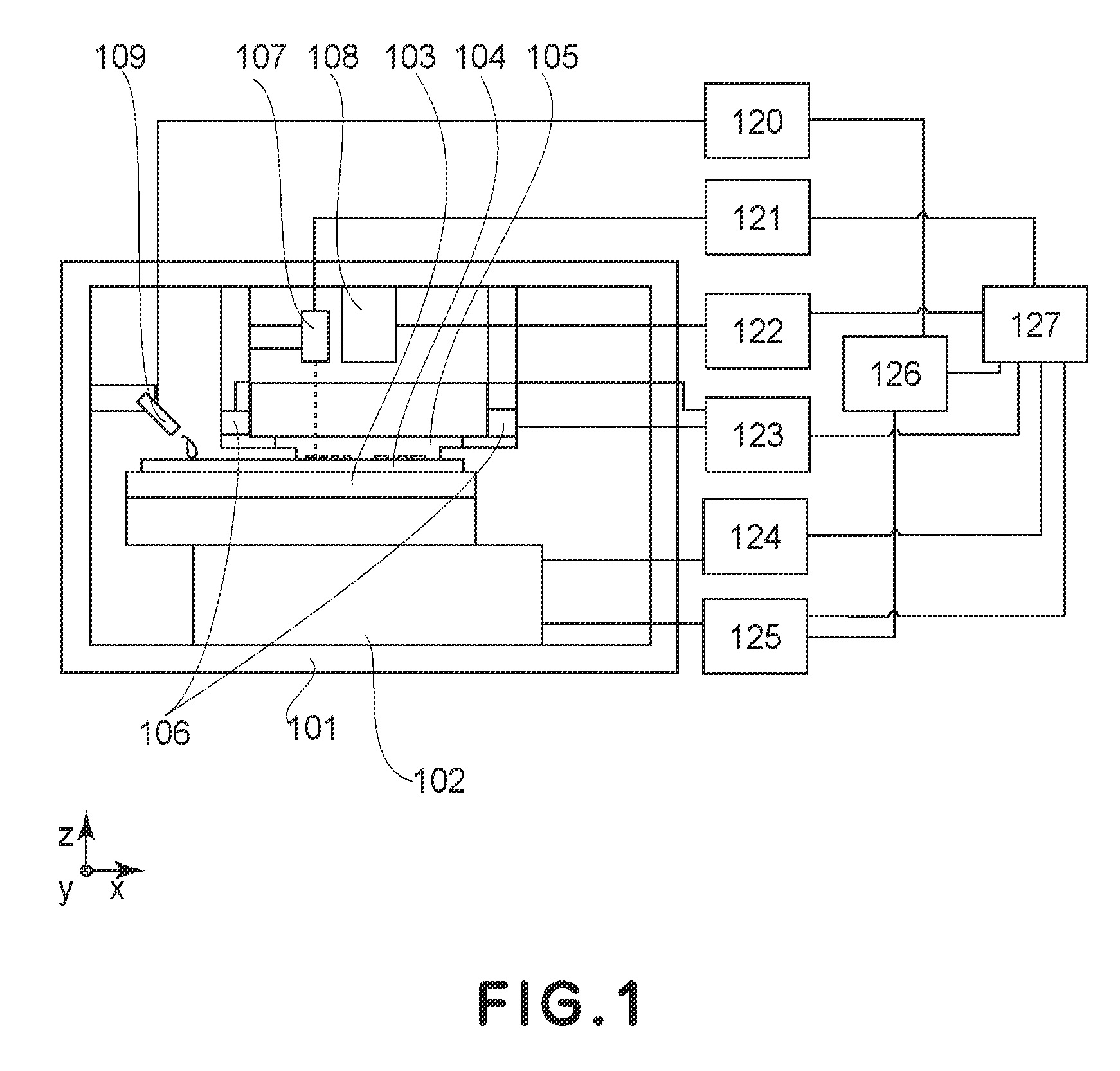
[0067]FIG. 1 shows the constitutional example of the pressure processing apparatus in this embodiment.

[0068]As shown inFIG. 1, in the pattern transfer apparatus of this embodiment, a mold 105 and a substrate 104 are disposed opposite to each other. The mold 105 is formed of a transparent material and has a desired imprint pattern at a surface facing the substrate 104. The mold 105 is connected to a housing 101 via a load cell 106 and a member. The transparent material for the mold 105 can be appropriately selected from quartz, sapphire, TiO2, SiN, etc. The surface of the mold 105 facing the substrate 104 is ordinarily subjected to release treatment by effecting treatment with a silane coupling agent or the like.

[0069]A scope 107 is constituted by a lens system and a CCD (charge coupled device) camer...


PUM

PropertyMeasurementUnit
densityaaaaaaaaaa
depthaaaaaaaaaa
heightaaaaaaaaaa

Abstract

A pattern forming method for forming a pattern on a pattern forming material on a substrate by using an imprint pattern provided to a mold is constituted by preparing a substrate having thereon a pattern forming area, disposing the pattern forming material placed in an uncured state in the pattern forming area in a dispersion state at a plurality of positions at different intervals, and curing the pattern forming material in a state in which the pattern forming material is deformed in a shape corresponding to a shape of the imprint pattern provided to the mold.

Description

FIELD OF THE INVENTION AND RELATED ART[0001]The present invention relates to a pattern forming method for forming a pattern on a pattern forming material on a substrate by using an imprint pattern provided to a mold (or a template) and also relates to a pattern forming apparatus.[0002]In recent years, e.g., as proposed in Appl. Phys. Lett., Vol. 67, Issue 21, pp. 3114-3116 (1995) by Stephan Y. Chou et al., fine processing technology for transferring a minute structure provided on a mold onto a member to be processed such as a resin material or a metal material has been developed and has received attention. This technology is called nanoimprint or nanoembossing and provides a processing resolution on the order of several nanometers. For this reason, the technology has been expected to be applied to next-generation semiconductor manufacturing technologies in place of light exposure devices such as a stepper, a scanner, and the like. Further, the nanoimprint technology is capable of co...

Claims


Application Information

Patent Timeline
Patent Type & Authority Patents(United States)
IPC IPC(8): B29C43/02B29C71/00
CPCB82Y10/00B82Y40/00G03F7/0002B81C1/0046Y10S977/887
Inventor OKUSHIMA, SHINGOSEKI, JUNICHI
Owner CANON KK
Why Eureka
Try Eureka