
System and method for improved visualization and debugging of constraint circuit objects

a constraint circuit and object technology, applied in the field of electronic circuit design, can solve the problems of too much to be managed manually, constraints are often portrayed in a manner that does not sufficiently aid the designer in visualizing the relationships imposed, and the designer's decision

Active Publication Date: 2011-01-04
CADENCE DESIGN SYST INC
View PDF3 Cites 48 Cited by
  • Summary
  • Abstract
  • Description
  • Claims
  • Application Information

AI Technical Summary

Benefits of technology

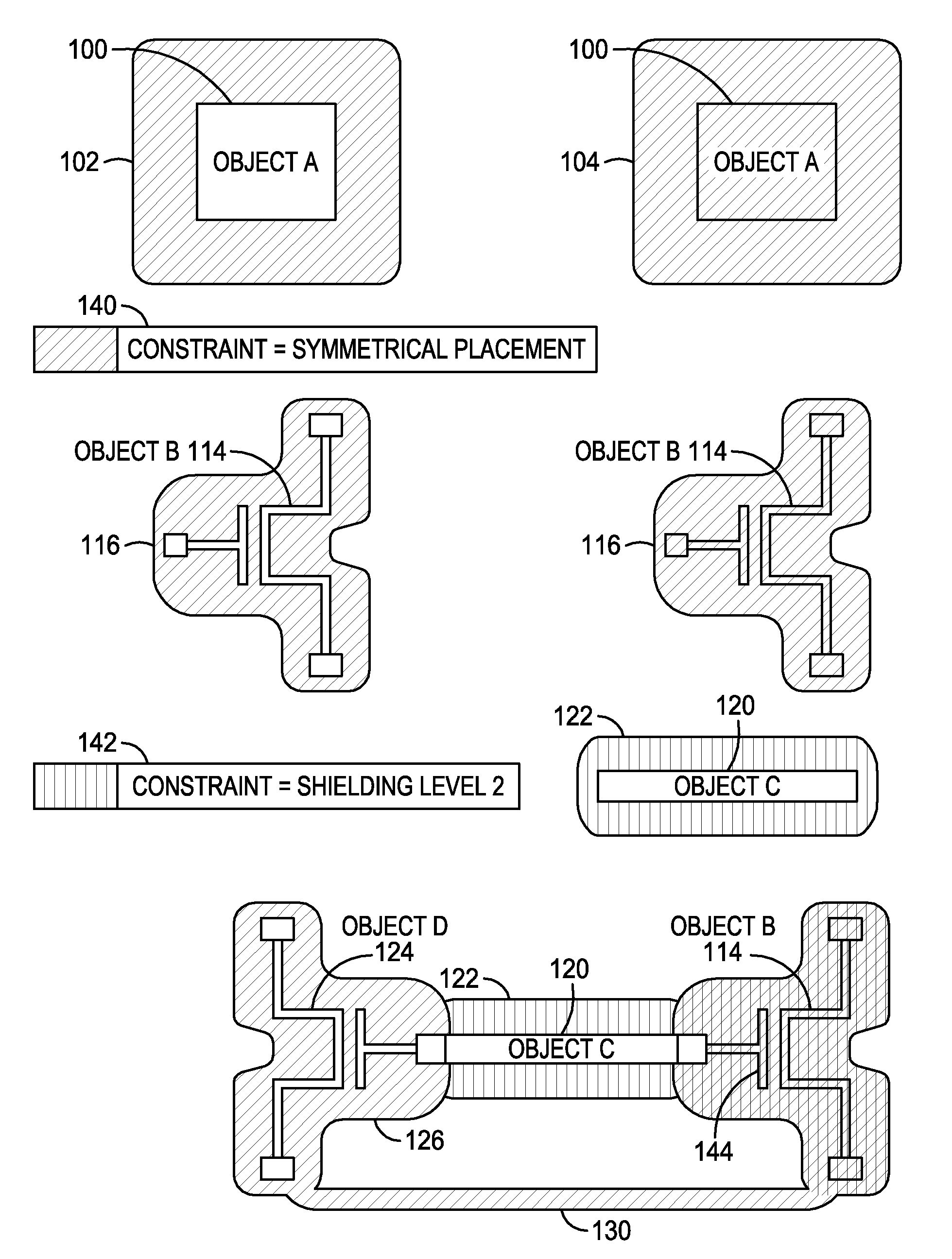
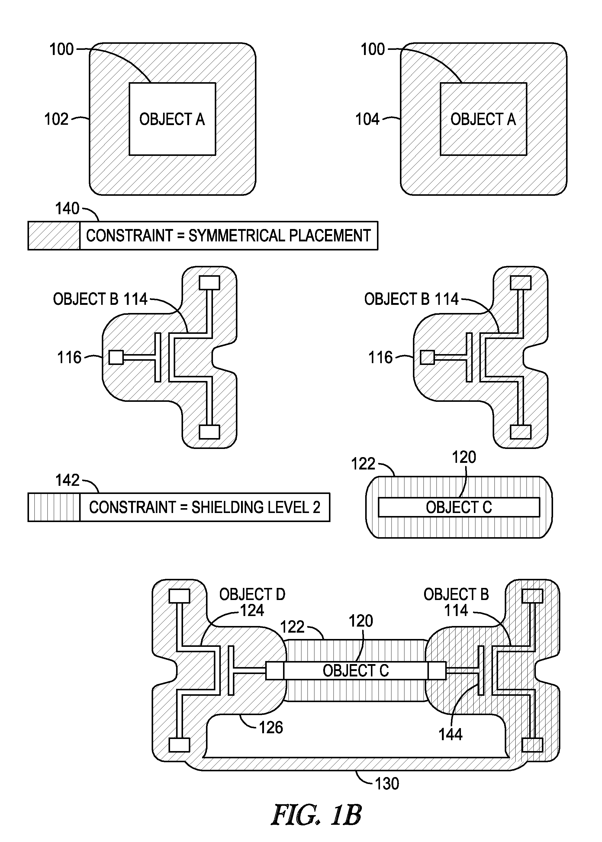
[0015]In general, in a first aspect, the invention features a computer-enabled method to produce a display of a design constraint on a computer screen in an Electronic Design Automation tool. The method includes producing a display of a first highlight feature on the screen in the proximity of a first design object, where the first highlight feature represents the association of a constraint with the first design object, at least a portion of the first design object remains visible while the first highlight feature is displayed, and the visual appearance of the first highlight feature indicates an attribute of the constraint. Embodiments of the invention may include one or more of the following features. The first highlight feature may have a color that indicates the type of the constraint, and the first highlight feature may be transparent. The first highlight feature may have a fill style that indicates the type of the constraint. The fill style may include cross-hatching, randomized stippling, a dashe...

Problems solved by technology

However, smaller geometries, growth in complexity, design rules, and constraints all contribute to a deluge of information—too much to be managed manually.
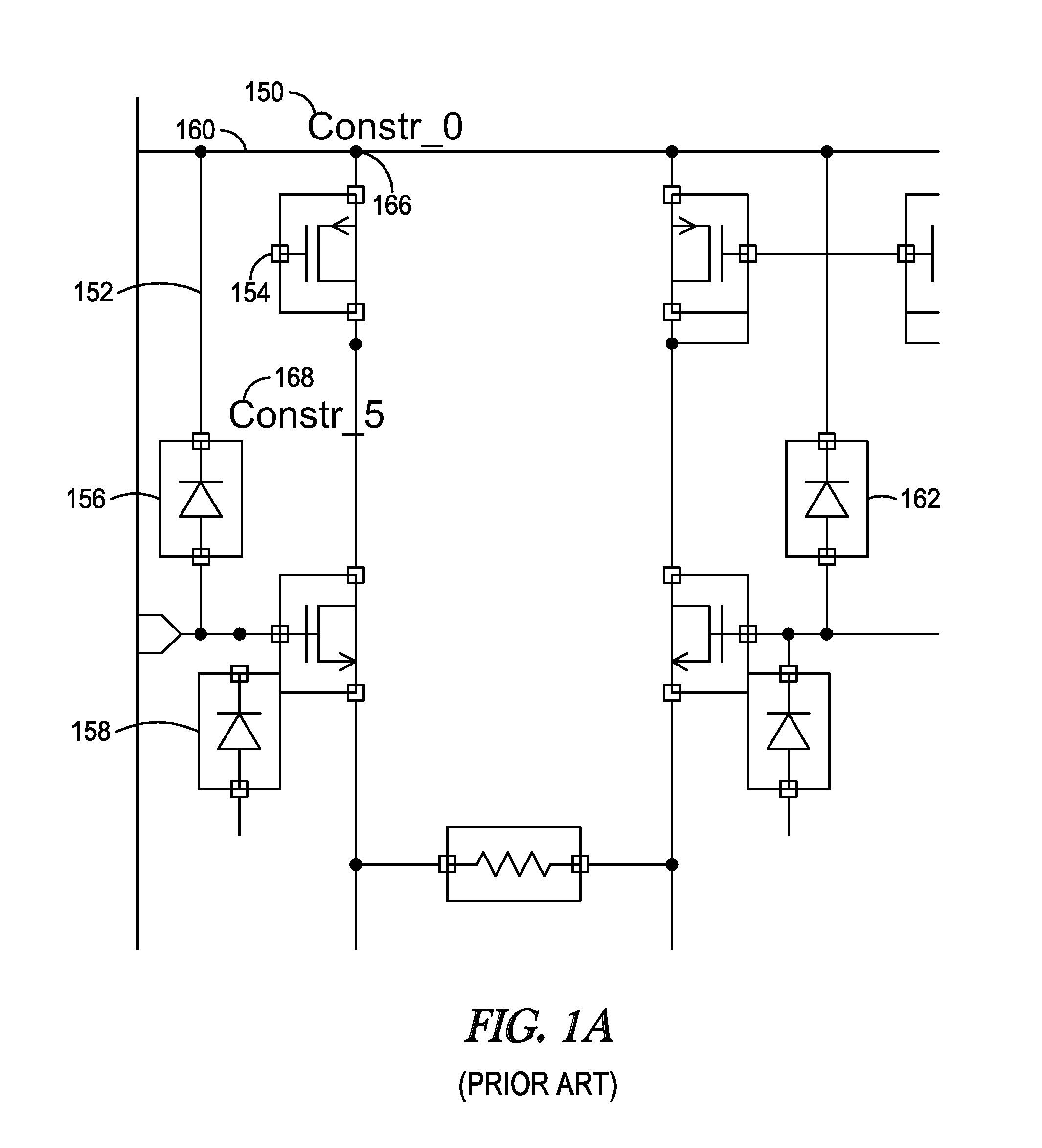
However, as constraints may store and depict relationships between design objects, these constraint relationships often are not presented in a manner that makes such relationships readily apparent.
In particular, constraints often are portrayed in a manner that does not sufficiently aid the designer in visualizing the relationships imposed.
This inability to readily perceive what constraints have been annotated on the design may result in a designer's decision to run through and iterate on the design's physical realization in order to understand the constraint.
However, often this list is very long and difficult to unravel, and as constraint names are insufficient by themselves, a mental leap is required to locate the corresponding constraint members in the design.
In addition, as the constraint relationships are not specially rendered or visualized on the canvas, the table-based widget approach also requires the designers to simultaneously keep track of the location and orientation of the actual design object and its proximity to other objects during interactive design editing.
This problem becomes more severe as the number of design constraints increases, making it more difficult for the designer to manually locate the design objects and then keep track of them.
Unfortunately, there have been shortcomings with prior constraint highlighting techniques.
Therefore, the prior highlighting approach often causes the actual device shapes to be obscured.
If there are additional highlight objects (e.g., textual annotations for constraint and member names) in use to impart special meaning to highlighted design objects, they too obscure the visible design areas.
This is often a problem when the constraint has to be visualized for a prolonged duration.
Further, an attempt to highlight an object associated with multiple constraints in more than one color generally causes the object to be highlighted with the last applied color, which makes it difficult for the designer to see what other constraints apply to a design object.
Moreover, the prior highlighting method typically draws the highlighted object shape in the same width as the un-highlighted object, which is often too narrow to visually stand out.
Other limitations include the inability to visualize other forms of interconnection between devices (or group relationships) in a way that does not obscure the spatial and electrical relationships.
The prior technique also fails to adequately show relationships that involve objects not displayed in the current view, such as relationships between objects on different levels of the design hierarchy.
Note that changing the colors of the design objects interferes with the appearance of the circuit design and may result in loss of information or confusion.
If the original, non-highlighted color of the design object conveys visual information about that design object, then replacing the color will result in loss of that visual information.
Other visual aspects of the prior highlighting method typically interfere with the appearance of the circuit design.

Method used


Image

  • System and method for improved visualization and debugging of constraint circuit objects
  • System and method for improved visualization and debugging of constraint circuit objects
  • System and method for improved visualization and debugging of constraint circuit objects

Examples


Embodiment Construction

[0077]The following description is presented to enable any person skilled in the art to make and use the invention, and is provided in the context of particular applications and their requirements. Various modifications to the preferred embodiments will be readily apparent to those skilled in the art, and the generic principles defined herein may be applied to other embodiments and applications without departing from the spirit and scope of the invention. Moreover, in the following description, numerous details are set forth for the purpose of explanation. However, one of ordinary skill in the art will realize that the invention might be practiced without the use of these specific details. In other instances, well-known structures and devices are shown in block diagram form in order not to obscure the description of the invention with unnecessary detail. Thus, the present invention is not intended to be limited to the embodiments shown, but is to be accorded the widest scope consist...


PUM


Abstract

Features are provided for graphically representing constraints on design objects in an Electronic Design Automation tool. A particular constraint on one or more circuit objects is displayed as a highlighted region that extends to each visible circuit object to which the constraint applies. Attributes of the highlighted region, such as density and thickness, may proportionally represent attributes of the constraint, such as a strength or distance specified by the constraint. The highlighted region is superimposed on or around circuit objects. The highlighted region may be a halo, which is a partially transparent region filled with a color. Multiple regions that represent the same type of constraint or relationship are connected by line segments, providing the ability to visualize groups of constrained objects, including groups that span levels of a hierarchical design. Intersecting highlighted regions are blended together using techniques such as alpha blending.

Description

BACKGROUND OF THE INVENTION[0001]1. Field of the Invention[0002]The invention relates to the design of electronic circuits and more particularly to methods for visualizing constraints in electronic circuit designs.[0003]2. Description of the Related Art[0004]Electronic Design Automation (EDA) tools allow circuit designers to define constraints on the objects in a circuit design, such as transistors and wires. A constraint is associated with one or more design objects, and may represent relationships among design objects. For example, in the context of the EDA domain, constraints are ordinarily associated with design objects such as devices, pins, terminals, instance terminals, and interconnect wires to represent design parameters for the design objects, and to represent relationships or requirements imposed by the design specification on the objects.[0005]Constraints allow designers to bring consistency into the design flow and achieve structures which are known to the designer to b...

Claims


Application Information

Patent Timeline
IPC IPC(8): G06F17/50
CPCG06F17/5045G06F17/5068G06F30/39G06F30/30G06F30/392G06F2111/04
Inventor CHOPRA, AMITGEBBIE, IANO'RIORDAN, DONALDARORA, SUMITSONNARD, JEAN-DANIEL
Owner CADENCE DESIGN SYST INC
Learn More