Mounting structure of solar cell module

a solar cell module and mounting structure technology, applied in the direction of machine supports, heat collector mounting/supports, light and heating apparatus, etc., can solve the problem of low arrangement and achieve the effect of improving the installation efficiency of solar cell modules and improving workability

Inactive Publication Date: 2011-01-11
SHARP KK
View PDF14 Cites 124 Cited by
  • Summary
  • Abstract
  • Description
  • Claims
  • Application Information

AI Technical Summary

Benefits of technology

[0027]The technology can provide the mounting structure of the solar cell module that improves workability in an operation of mounting the solar cell module, and also improves installation efficiency of the solar cell module.

Problems solved by technology

This causes an area or region where arrangement efficiency of the solar cell modules is low.

Method used


Image

  • Mounting structure of solar cell module
  • Mounting structure of solar cell module
  • Mounting structure of solar cell module

Examples


Embodiment Construction

[0046]Referring to FIGS. 1 to 17, a mounting structure of a solar cell module will now be described. A solar cell device in the embodiment includes solar cell modules and a mounting device of the solar cell modules.

[0047]In this embodiment, the solar cell device is arranged on a roof of a house. For example, when longitudinal beams are arranged on the roof with a predetermined space therebetween, as disclosed in Japanese Patent Laying-Open No. 11-324259, the mounting structure of the solar cell modules is substantially the same as that in the prior art.

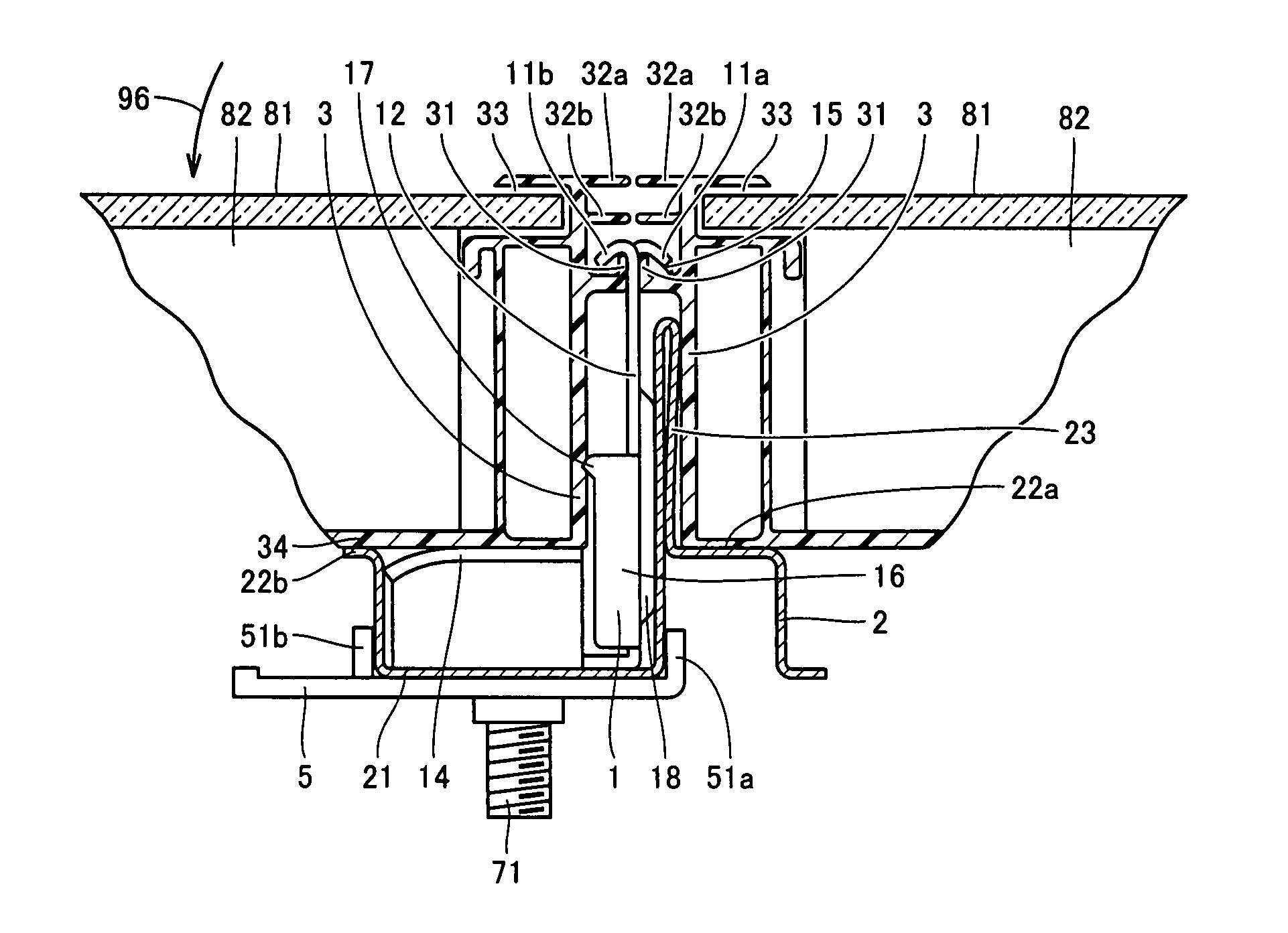
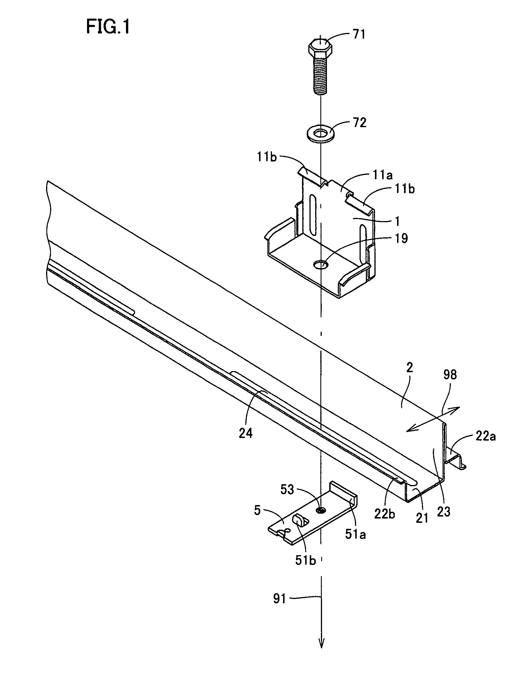
[0048]FIG. 1 is an exploded perspective view showing a part of the mounting structure of the solar cell module according to the embodiment, and particularly showing a part including a lateral beam and a fastening arranged thereon.

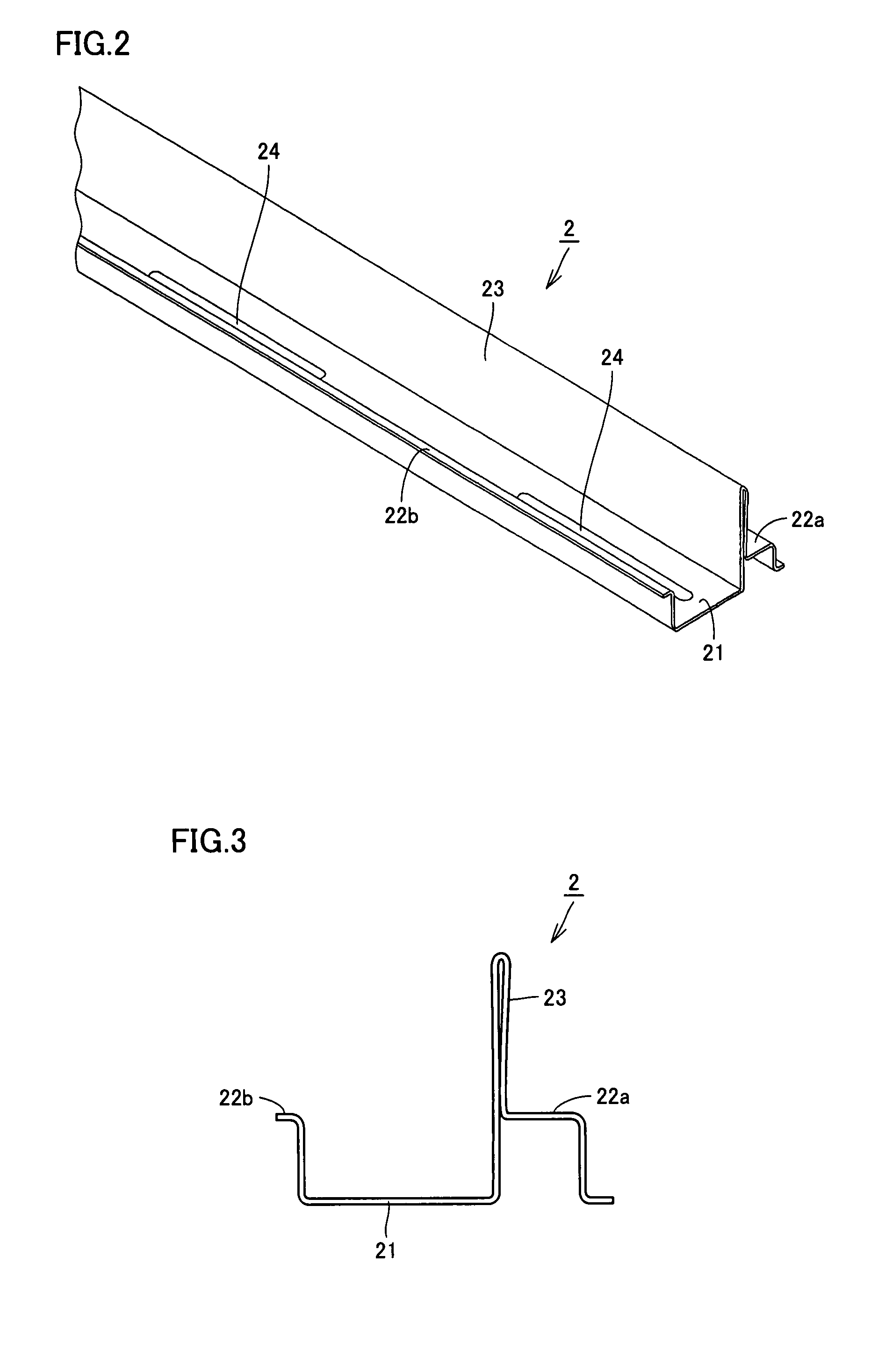
[0049]The mounting device of the solar cell module according to the embodiment includes a lateral beam 2 serving as a beam member, a fastening 1 that is a metal part for fixing or attaching the solar cell mod...


PUM


Abstract

A mounting structure of a solar cell module includes a fastening for mounting the solar cell module on a lateral beam. The fastening includes a body, and a plurality of hooks formed at an end of the body. The hooks have a hook having a form bent toward one side, having an end directed downward and serving as a first hook, and a hook having a form bent away from the one side, having an end directed downward and serving as a second hook. The hooks are opposed to and engaged with a projection of a hooked and L-shaped form formed on the solar cell module.

Description

[0001]This application is the U.S. national phase of International Application No. PCT / JP2006 / 305943 filed 24 Mar. 2006 which designated the U.S. and claims priority to JP 2005-111137 filed 7 Apr. 2005, the entire contents of each of which are hereby incorporated by reference.TECHNICAL FIELD[0002]The present technology relates to a mounting structure of a solar cell module.BACKGROUND ART[0003]A solar cell device includes a solar cell module and a support device, and has a structure in which the solar cell module is supported on the support device.[0004]Some kinds of solar cell devices are arranged on roofs of buildings. In recent years, the solar cell devices for family use have been spreading, and a majority of them are arranged on roofs of personal buildings.[0005]Japanese Patent Laying-Open No. 11-68137 has disclosed a installing device for solar cell modules, in which lateral beams each having a C-shaped section are arranged on a roof with their openings directed upward, and the...

Claims


Application Information

Patent Timeline
Patent Type & Authority Patents(United States)
IPC IPC(8): E04D13/18
CPCF24J2/5207F24J2/5211F24J2/5245F24J2/5254F24J2/5262H02S20/00F24J2002/4661Y10T24/301Y02B10/12Y02E10/47Y02E10/50Y10T24/307F24J2002/5215F24S25/20F24S25/35F24S25/61F24S25/632F24S25/67F24S2025/6002F24S2025/801Y02B10/10
Inventor KOMAMINE, TATSUYAARAMAKI, YOSHIHIROOHKOSHI, YASUSHI
Owner SHARP KK
Why Eureka
Try Eureka