Passive removal of suction air for laminar flow control, and associated systems and methods

a technology of laminar flow control and suction air, applied in the direction of air-flow influencers, functional valve types, operating means/releasing devices of valves, etc., can solve the problems of significant aircraft drag and contribute to airplane drag

Active Publication Date: 2011-01-11
THE BOEING CO
View PDF46 Cites 36 Cited by
  • Summary
  • Abstract
  • Description
  • Claims
  • Application Information

AI Technical Summary

Problems solved by technology

A significant amount of aircraft drag is caused by boundary layers that build up on the exposed surfaces of the aircraft during flight.
The boundary layer build-up on the aircraft wings and / or other external surfaces causes skin friction and therefore significantly contributes to airplane drag.

Method used


Image

  • Passive removal of suction air for laminar flow control, and associated systems and methods
  • Passive removal of suction air for laminar flow control, and associated systems and methods
  • Passive removal of suction air for laminar flow control, and associated systems and methods

Examples


Embodiment Construction

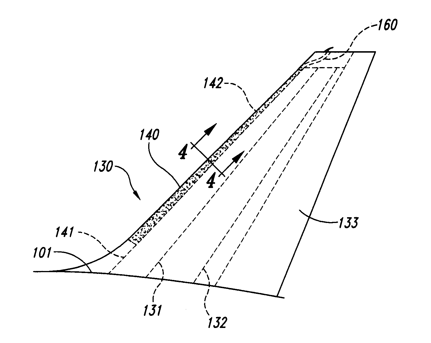
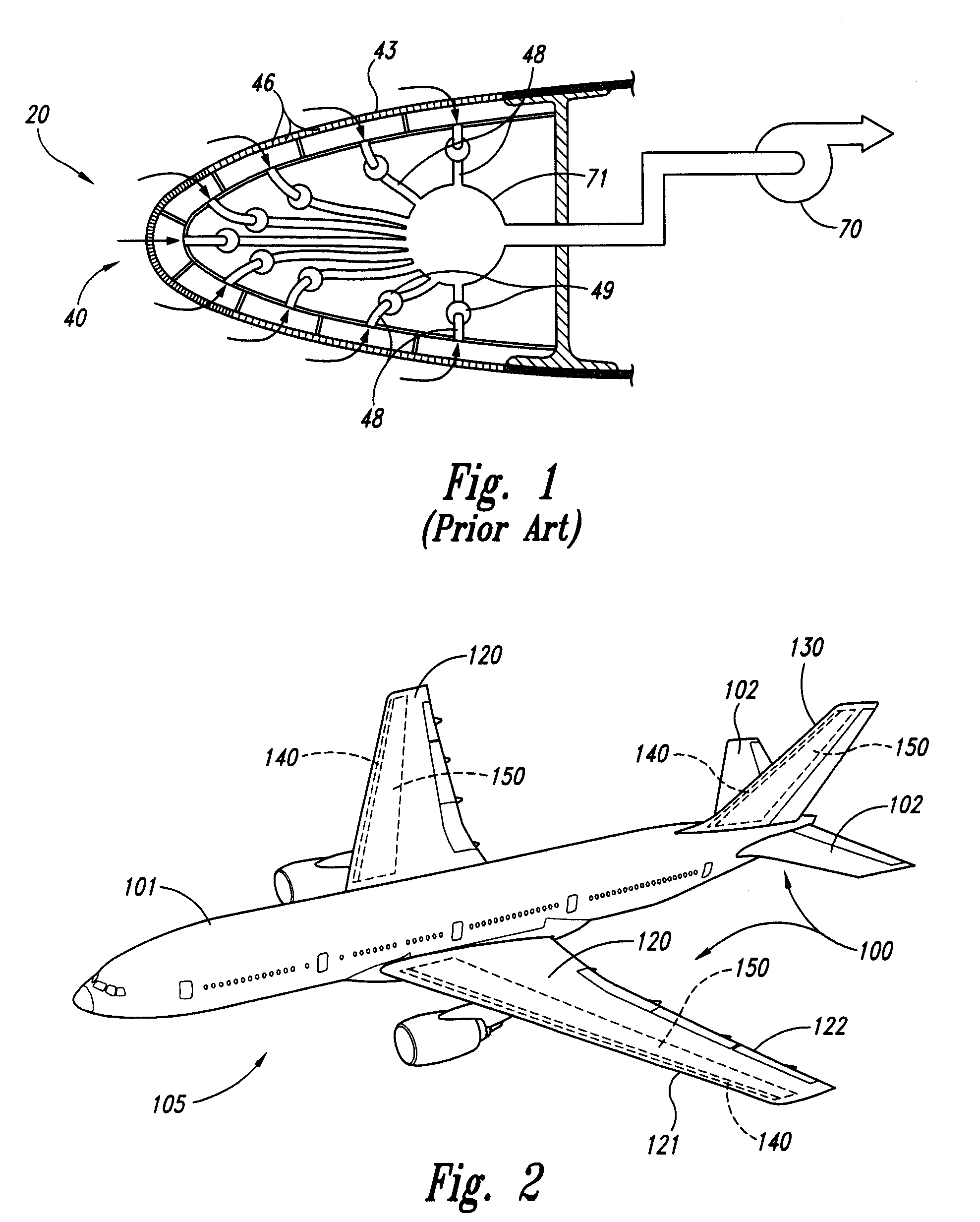
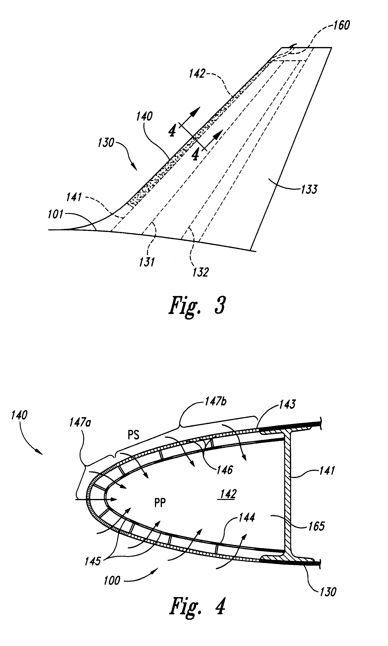
The following description is directed generally toward systems and methods for passively providing suction for laminar flow control at aircraft external surfaces. For example, several embodiments include drawing flow through the external surface to a common plenum and directing the flow overboard the aircraft without the use of a compressor or other active device. Several details describing structures or processes that are well-known and often associated with aspects of these systems and methods are not set forth in the following description for purposes of brevity. Moreover, although the following disclosure sets forth several embodiments of different aspects of the invention, several other embodiments can have different configurations or different components than those described in this section. For example, other embodiments may have additional elements and / or may delete several of the elements described below with reference to FIGS. 1-8D.

Several embodiments of the invention desc...


PUM


Abstract

Passive removal of suction air for producing a laminar flow, and associated systems and methods are disclosed. One such method includes forming a laminar flow region over an external surface of an aircraft by drawing air through the external surface and into a plenum. The method can further include passively directing the air from the plenum overboard the aircraft. For example, the air can be passively directed to a region external to the aircraft having a static pressure lower than a static pressure in the plenum, as a result of the motion of the aircraft. Flows from different sections of the external surface can be combined in a common plenum, and the corresponding massflow rates can be controlled by the local porosity of the external surface.

Description

TECHNICAL FIELDThe present disclosure is directed generally to techniques for passively removing suction air to create a laminar flow environment on aircraft external surfaces, and associated systems and methods.BACKGROUNDAircraft designers and manufacturers are under continual pressure to reduce the aerodynamic drag on aircraft surfaces, so as to increase aircraft performance and / or reduce aircraft fuel consumption. A significant amount of aircraft drag is caused by boundary layers that build up on the exposed surfaces of the aircraft during flight. A boundary layer is a thin film of low velocity, low dynamic pressure air located near a solid boundary and resulting from the air being at rest at the interface with the solid boundary. The boundary layer build-up on the aircraft wings and / or other external surfaces causes skin friction and therefore significantly contributes to airplane drag. Because laminar boundary layers create less friction at the aircraft surfaces than do turbule...

Claims


Application Information

Patent Timeline
Patent Type & Authority Patents(United States)
IPC IPC(8): B64C21/06
CPCB64C21/06Y02T50/166B64C2230/22B64C2230/20Y10T137/1842Y02T50/10
Inventor PARIKH, PRADIP G.
Owner THE BOEING CO
Why Eureka
Try Eureka