AI technical title is built by Patsnap AI team. It summarizes the technical point description of the patent document.
a carton and feature technology, applied in the field of enclosed paperboard cartons, can solve the problems of affecting the quality of the product, the carton cannot be easily moved from one location to another, and the cans will fall out, so as to achieve the effect of easy opening and weakening the structural integrity of the carton
Active Publication Date: 2011-01-25
GRAPHIC PACKAGING INT
View PDF30 Cites 12 Cited by
Summary
Abstract
Description
Claims
Application Information
AI Technical Summary
This helps you quickly interpret patents by identifying the three key elements:
Problems solved by technology
Method used
Benefits of technology
Benefits of technology
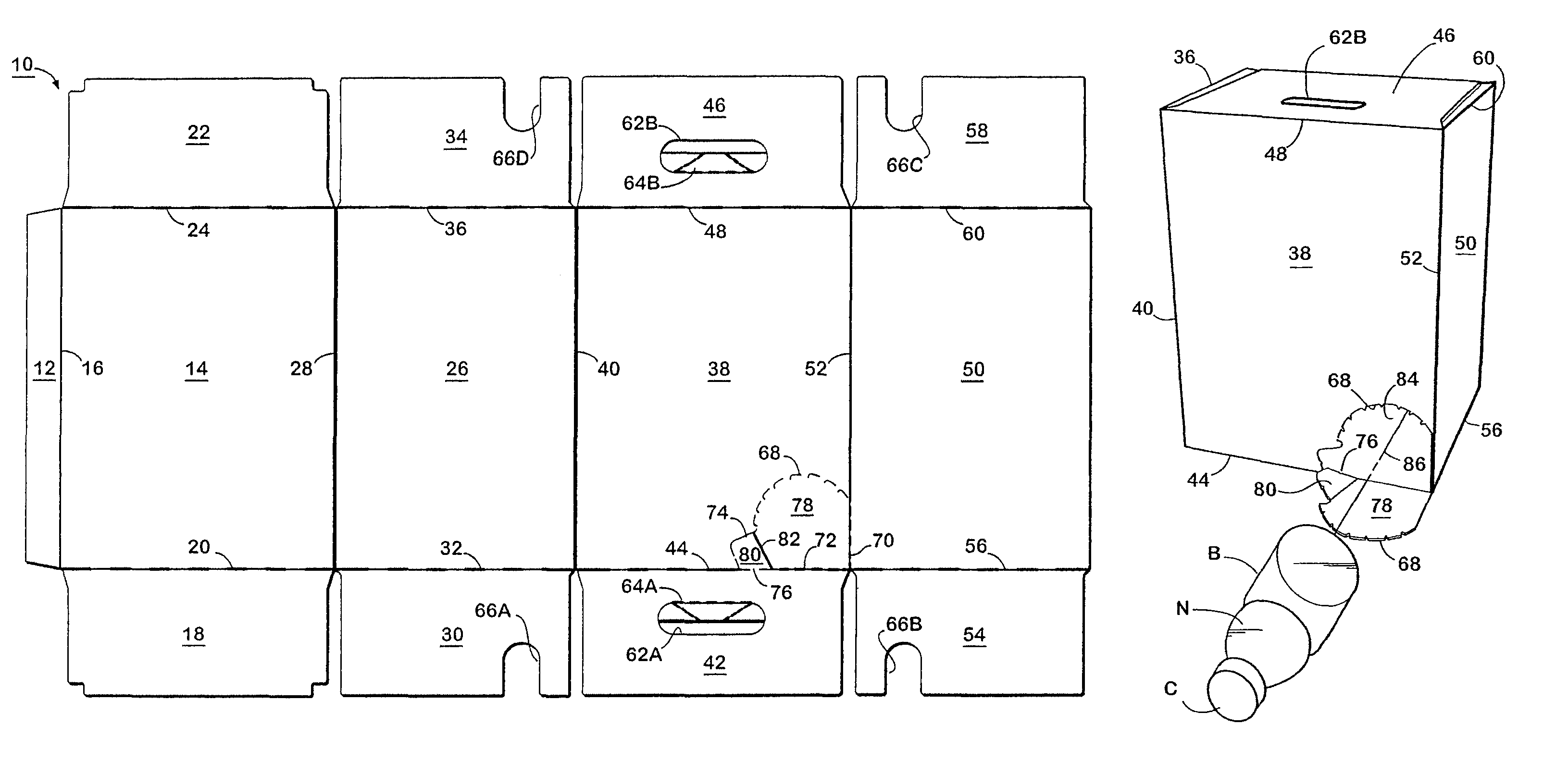
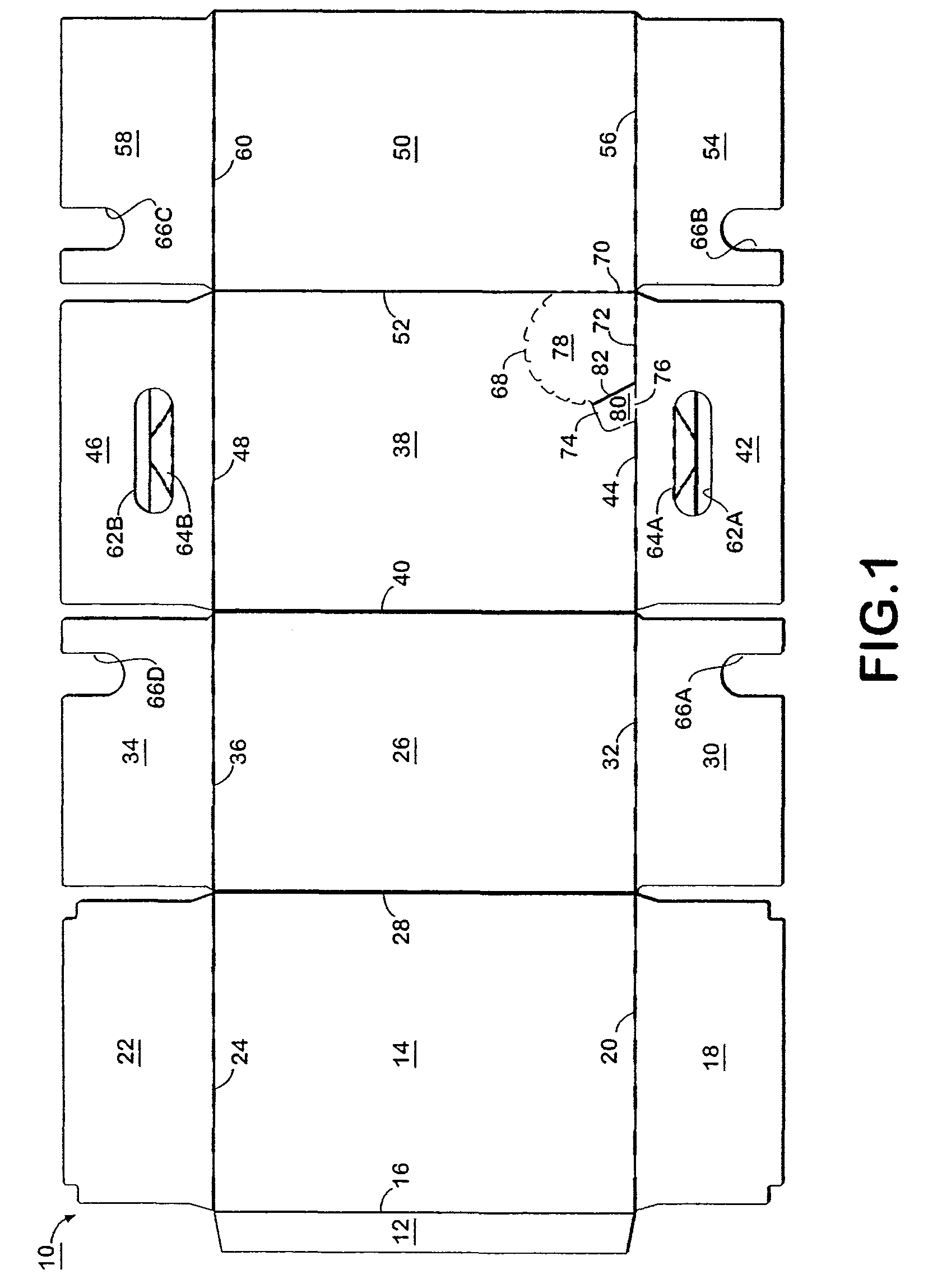
[0010]It is an object of this invention to provide a dispenser or opening in a carton for the removal of bottles that have a smaller diameter at the top than at the bottom. It is a further object of this invention to provide a dispenser that is resistant to being accidentally opened during handling or stacking of the cartons by the weight of a container adjacent the dispenser flap. It is the further object to provide a dispenser that can be easily opened but is resistant to being accidentally opened. It is another object of this invention to provide a dispenser so that bottles with a smaller neck than body can be grasped through the dispenser and removed without the necessity of having a second dispenser in longitudinal alignment with this dispenser. In other words, it is an object of this invention to provide a single dispenser without the necessity of a second dispenser that weakens the structural integrity of the carton. It is still another object of this invention to provide a carton with a dispenser that will permit the carton to be moved from one location to another after it has been opened without discharging containers. An additional object is to provide a carton with a dispenser whereafter the removal of the container, another container will move into position with respect to the dispenser for easy removal.
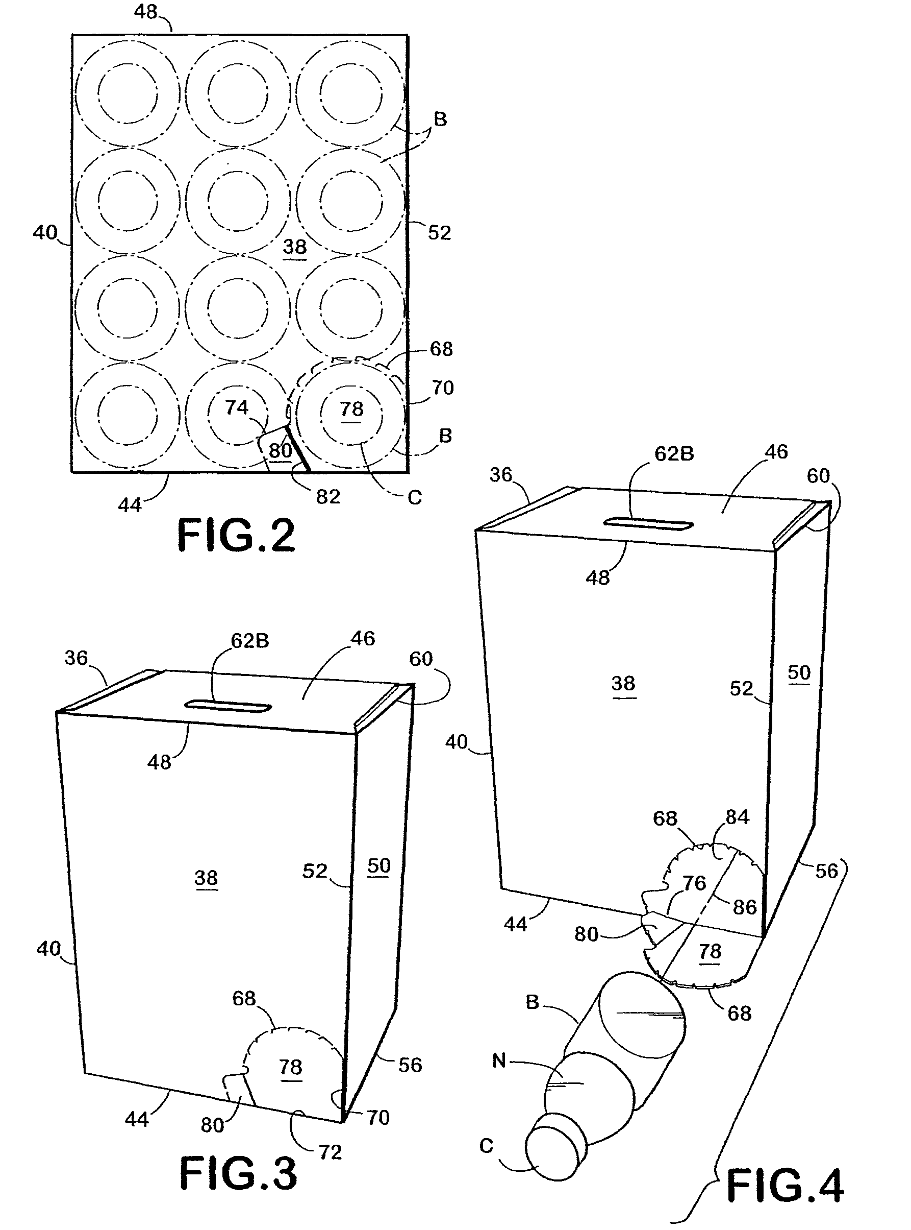
[0013]The dispenser flap on this carton is opened to provide the dispenser opening by placing the carton on end with the dispenser being located near such end. Once a dispenser flap has been removed by pulling on the pull tab, a person may remove a bottle by reaching into the dispenser opening and pulling a bottle by the neck which has a smaller diameter than the body. Other bottles roll towards the dispenser opening after the removal of the bottle. It is necessary to place the dispenser opening in the top panel as the bottles with smaller necks and bodies should be stacked in the carton in an upright position to prevent spillage and damage. The removal of these bottles is facilitated by virtue of the small diameter of the neck of the bottle being located near the top panel where the dispenser opening is located. It has been discovered that it is not necessary to have two openings in each side panel on the same longitudinal axis in respect to bottles with smaller necks than bodies.
[0015]This carton can be constructed by gluing, taping, stapling and the like, or by locking. It may have handles in the end panels for carrying so that the bottles are carried in an upright position to help minimize damage to the carton or the containers contained therein.
Problems solved by technology
The necessity of having two ports tends to weaken the structural integrity of the Miller carton.
This carton cannot be easily moved from one location to another after both ports have been opened without a risk that the cans will fall out.
This carton is not adapted for use with bottles, because of the necessity of grasping the ends of the container for removal.
In addition, it is not adapted for carrying cans once the carton has been opened as they are likely to roll out of the dispenser.
Method used
Image
Click on the blue label to locate the original text in one second.
Reading with bidirectional positioning of images and text.
Examples
Embodiment Construction
[0022]The present invention is intended primarily for use with bottles or cans that have a top with a smaller diameter than the bottom. The blank 10 is formed from a foldable sheet material, such as paperboard. The blank 10 has a glue flap 12 which is attached to the bottom panel 14 by fold line 16. Bottom end flaps 18 and 22 are attached to bottom panel 14 by fold lines 20 and 24 respectively. Bottom panel 14 is attached to side panel 26 by fold line 28. Bottom panel 26 is attached to side end flaps 30 and 34 by fold lines 32 and 36 respectively. Side panel 26 is attached to top panel 38 by fold line 40. Top panel 38 is attached to top end flaps 42 and 46 by fold lines 44 and 48 respectively. Side panel 50 is attached to top panel 38 by fold line 52. Side panel 50 is attached to side end flaps 54 and 58 by fold lines 56 and 60 respectively.
[0023]This carton may be provided with handles 62A and 62B formed in top end flaps 42 and 46 respectively. The handles 62A and 62B may have hand...
PUM
Property
Measurement
Unit
size
aaaaa
aaaaa
shape
aaaaa
aaaaa
perimeter
aaaaa
aaaaa
Abstract
A carton with a new dispenser that can be opened by a pull tab with this dispenser flap being placed in a corner of the top panel of the carton so that it is adjacent to the tops of the small necks of the bottles for easy opening and removal or for opening and reclosing. The dispenser flap is held in position by resistant tear lines but can be easily removed by an attached pull tab that is loosely connected to the top panel.
Description
CROSS-REFERENCE TO RELATED APPLICATIONS[0001]This application is a continuation-in-part of U.S. patent application Ser. No. 11 / 069,238 filed Mar. 1, 2005, now U.S. Pat. No. 7,331,507 which is a continuation of U.S. patent application Ser. No. 10 / 626,234 and filed Jul. 24, 2003, incorporates the disclosure thereof, now U.S. Pat. No. 6,869,009, issued Mar. 22, 2005, which is a continuation-in-part of U.S. patent application Ser. No. 10 / 360,232 filed Feb. 6, 2003, and incorporates the disclosure thereof, now U.S. Pat. No. 6,604,677, issued Aug. 12, 2003, all of which are incorporated herein by reference in their entireties.BACKGROUND OF THE INVENTION[0002]1. Field of the Invention[0003]The present invention relates generally to an enclosed paperboard carton capable of enclosing containers with a top of a smaller diameter than the bottom, which carton has a unique opening and dispensing feature in the top panel which allows the containers to be removed or dispensed one at a time by gras...
Claims
Application Information
Patent Timeline
Application Date:The date an application was filed.
Publication Date:The date a patent or application was officially published.
First Publication Date:The earliest publication date of a patent with the same application number.
Issue Date:Publication date of the patent grant document.
PCT Entry Date:The Entry date of PCT National Phase.
Estimated Expiry Date:The statutory expiry date of a patent right according to the Patent Law, and it is the longest term of protection that the patent right can achieve without the termination of the patent right due to other reasons(Term extension factor has been taken into account ).
Invalid Date:Actual expiry date is based on effective date or publication date of legal transaction data of invalid patent.

