Transport of aggregated client packets

a client packet and packet technology, applied in the field of optical communication, can solve the problems of large packet arrival jitter, variable accumulation time of client packets, temporal variation of delay, etc., and achieve the effect of high burst of forwarded packet flow

Active Publication Date: 2011-01-25
META PLATFORMS INC
View PDF15 Cites 6 Cited by
  • Summary
  • Abstract
  • Description
  • Claims
  • Application Information

AI Technical Summary

Benefits of technology

[0015]This is typically not the case in packet transport networks with packet accumulation and aggregation of accumulated packets in a container, e.g. in burst or frame switched networks. Such networks are still in research and not yet fully standardized. In such networks multiple small client packets are aggregated into large containers to save switching overhead in the network core.
[0018]In burst switched networks and frame switched networks a larger size container (i.e. a burst in case of a burst switched network, and a frame in case of a frame switched network) containing multiple client packets is used which normally waits until completion before being transmitted. In turn, completion of the container depends on the actual traffic load. Idle pattern between packets, e.g. in case of low traffic load, are generally not used. The client packets are encapsulated in the container one after another, regardless of the relative timing at the ingress node. Filling pattern may occur only at the end of the container. At the egress node, the encapsulated packets in the container are unloaded and released to the access network (or metro network). However, at this point the original timing between the packets is not available any more. In dependency of the traffic load, the client packets may be lumped together in bursts. This results in a high burden on the downstream network buffers. In particular in case of low traffic load, a high burstiness of the packet flow at the egress node may easily occur. Such high burstiness did not exist when the packets entered the ingress node.
[0023]Hence, it is an object of the present invention to provide a method for transmitting client packets via a packet transport network, with the method allowing for reduced header processing capabilities. The method should overcome the problem of high burstiness of the flow at the egress node as discussed above. It is a further object of the present invention to provide corresponding network elements for the ingress and egress nodes of such packet transport network and to provide such network as such.
[0026]In the nodes in between only the container headers and not the packet headers may be processed. Thus, only the headers of the containers and not the headers of the encapsulated packets are visible to the core network. Such aggregation may reduce the worst case packet header processing (e.g. for 10 Gbit / s or 100 Gbit / s Ethernet links) at least by a factor of 100.
[0029]The header count may be limited to an essentially constant (i.e. independent of the actual traffic) low level. In case of low load e.g. only 1 or 2 packets are contained in a container, whereas in case of high load many packets are encapsulated in a container. In both cases, the core network has only to process the header of the container, irrespective of the container load. This reduces the header processing effort in the transport network, in particular in the switches of the transport network. Thus, the header processing power of the network elements in the transport network may be reduced or at the same processing power the gross throughput can be increased.
[0031]The proposed method provides the advantage that the timing of the received packets is not lost when aggregating the packets into a container. Instead, timing information characterizing the timing of the received packets at the ingress node is determined and transmitted to the egress node. Thus, based on the transmitted timing information, the timing may be restored at the egress node such that the timing of the extracted packets at the egress node essentially corresponds to the timing of the received packets at the ingress node. Thus, high burstiness of the forwarded packet flow at the egress node is avoided, thereby avoiding the problem of temporary overload at the far end. In other words, at the unloading stage the packet arrival process may be mimicked by reestablishing the correct departure distances as stored together with the packets.

Problems solved by technology

This causes problems for lower-order networks downstream of the egress-node of the core network.2. Variable traffic load at the ingress node of such core network further results in variable accumulation times for accumulating packets for a container.
This uncertainty in the accumulation time results in temporal variations of the delay between containers and thus in large jitter of the packet arrival after de-aggregation.
Such jitter is e.g. a problem for steaming applications that need constant packet time distances.

Method used


Image

  • Transport of aggregated client packets
  • Transport of aggregated client packets
  • Transport of aggregated client packets

Examples


first embodiment

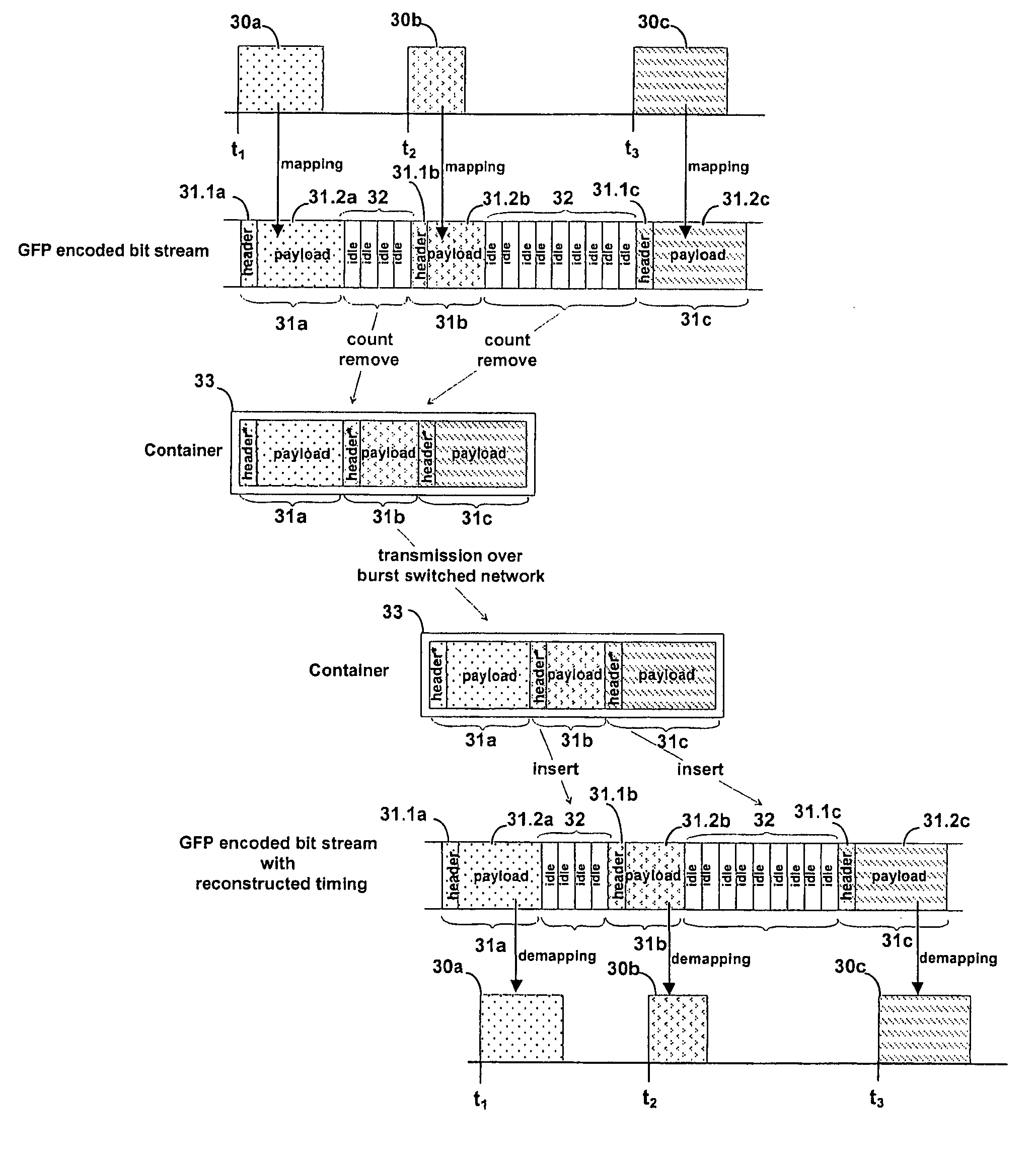
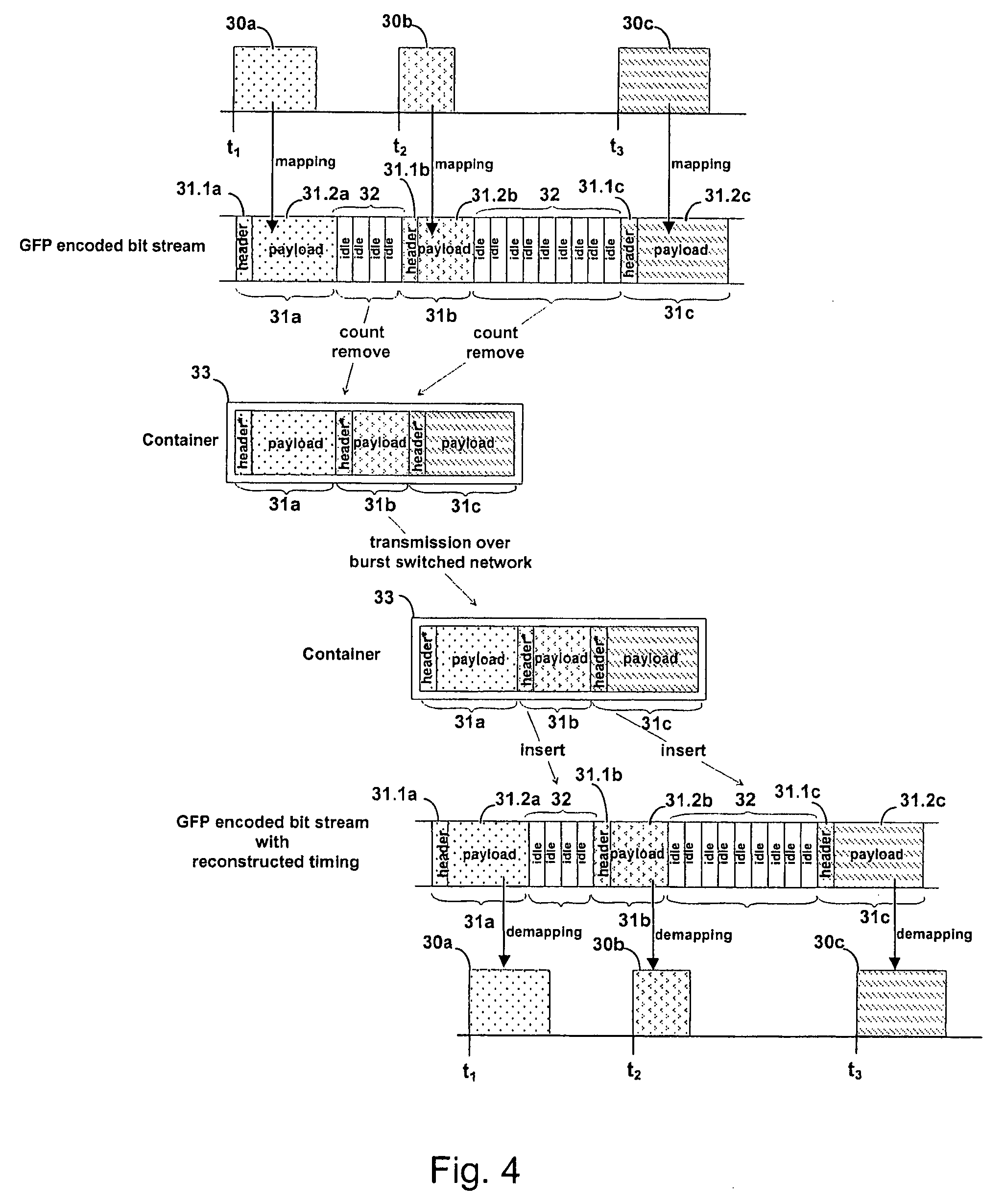
[0069]FIGS. 1 to 3 were already discussed above. FIG. 4 illustrates the inventive method of transmitting client signals via a packet transport network with packet aggregation, e.g. a burst switched network. The method is implemented by means of an extension of the standard Generic Framing Procedure (GFP) as will be explained in the following.

[0070]Client packets 30a, 30b, 30c arrive at an ingress node of the network, e.g. at various times t1, t2 and t3. In FIG. 4, the client packets 30a, 30b, 30c relate to different client signals. The client packets 30a, 30b, 30c may be, e.g. Ethernet frames and / or IP / PPP frames.

[0071]The client packets 30a, 30b, 30c are encoded to a GFP encoded bit stream, i.e. the packets 30a, 30b, 30c are mapped to GFP client data frames 31a, 31b, 31c. Further, GFP idle frames 32 are placed between the GFP client data frames 31a, 31b, 31c to compensate for the gaps between the client packets 30a, 30b, 30c.

[0072]Two mapping modes exist in GFP: frame-mapped GFP (...

second embodiment

[0082]As discussed above, variable traffic load at the ingress node of such network further results in variable accumulation times for accumulating packets assigned to a container. This uncertainty in the accumulation time results in temporal variations of the delay between subsequent containers at the egress node and thus in jitter of packet arrival after de-aggregation. Such variation in the accumulation time due to traffic variations may be compensated as discussed below in the inventive method. As a result not only the relative timing of packets in the same container but also the relative timing of packets in different containers is reconstructed at the egress node.

[0083]The second embodiment of the inventive method as illustrated in FIG. 5 performs aggregation of client packets into containers and de-aggregation of client packets from a transmitted container by the following steps:[0084]1. At an ingress node of a high speed packet transport network, incoming client packets 40a-...


PUM


Abstract

The invention relates to a method for transmitting one or more client signals via a packet transport network. According to the method, packets of the one or more client signals are received at an ingress node of the network. Timing information characterizing the timing of the received packets is determined and the received packets are mapped into a container. The container and the timing information are transmitted via the network. At an egress node of the network, the packets are extracted from the container and the packets are timed for further transmission based on the transmitted timing information.

Description

[0001]The invention is based on the priority applications EP08155314.1 and EP07291541.6, which are hereby incorporated by reference.FIELD OF THE INVENTION[0002]The invention relates to optical communication, in particular to a method of transmitting aggregated packets of one or more client signals via a packet transport network. Further, the invention relates to network elements for such packet transport network and to a packet transport network as such.BACKGROUND OF THE INVENTION[0003]In packet networks, the elements of the triplet of packet size, data rate and forwarding delay are intrinsically tied to each other. Packets, e.g. Ethernet packets, are typically well adapted in size for the needs of end user applications, in particular for providing a forwarding delay acceptable for the application. At the typical data rates of the end user, the packet size is dimensioned to produce forwarding delays below the human temporal perception horizon. E.g. an Ethernet packet having a size o...

Claims


Application Information

Patent Timeline
Patent Type & Authority Patents(United States)
IPC IPC(8): H04J3/24H04J3/06H04L12/56H04L12/54H04L47/43
CPCH04J3/1617H04L12/5693H04L47/10H04L47/28H04L47/56H04L47/627H04J2203/0089H04L2012/5649H04L2012/5674H04L2012/5679H04L47/50
Inventor LAUTENSCHLAEGER, WOLFRAM
Owner META PLATFORMS INC
Why Eureka
Try Eureka