
Method and system for signal processing, for instance for mobile 3D graphic pipelines, and computer program product therefor

a signal processing and pipeline technology, applied in the field of 3d graphic technology, can solve problems such as insufficient pixel availability, inability to adequately consider possible approaches, and annoying aliasing, and achieve the effect of reducing aliasing artifacts in computer graphics

Active Publication Date: 2011-01-25
STMICROELECTRONICS SRL
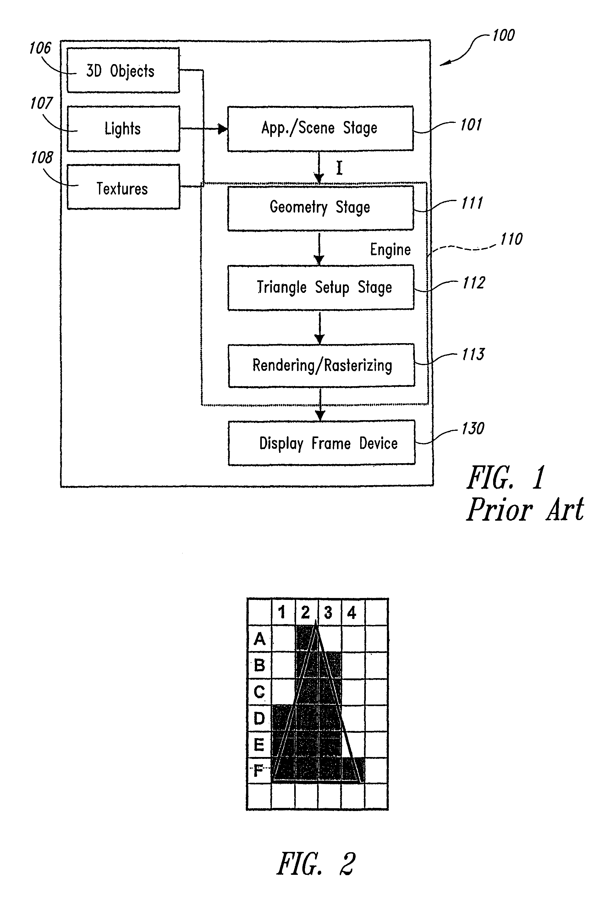
View PDF7 Cites 8 Cited by
  • Summary
  • Abstract
  • Description
  • Claims
  • Application Information

AI Technical Summary

Benefits of technology

[0161]One embodiment of the present invention provides a graphic engine arrangement adapted to reduce aliasing artifacts in computer graphics.

Problems solved by technology

That effect, which is mostly manifest at polygon edges, is due to lack of sufficient pixel availability to render smoothly lines, points and polygon edges as defined mathematically.
This approach does not take in consideration adequately the possibility for a pixel to be covered partially by an object as it may typically happen at object edges.
Aliasing is in fact very annoying.
In particular when the scene has moving portions, the artifacts become evident as flickering details and instability of the contours.
This decreases the realism perceived.
The human eye can detect artifacts up to about 600 points per inch but unfortunately no commercial monitor has such resolution.
The stages have a varying complexity, which varies from one stage to another: typically stages that process and affect pixels (e.g., the late stages of the pipeline) are more complex than those that process the 3D scene details.
Quads, instead, are not planar and more difficult to manage.
These operations are those demanding most of the computational power.
A very detailed and realistic lighting scheme easily becomes very complex from the computational viewpoint to be implemented in a 3D pipeline.
These are placed in the equations for the lighting model which, even though simplified, turns out to be a highly complex one especially if more lights influence the scene.
On the other side the quality is usually very poor since there is a color discontinuity between adjacent triangles.
However, specular reflections (highlights) are not rendered realistically.
OpenGL does not support this approach since the normals are discarded after prospective projection.
A limitation of shading lies in the impossibility of simulating very high details unless the model geometry is significantly modified.
As indicated in the introductory portion of this application, when rendering a frame, due to the discrete nature of its rows and columns, aliasing will decrease the perceived quality.
This happens since the motion is not sampled properly from time to time.
However, a resolution change is not always feasible.
However, due their discrete nature, post-filtering methods cannot remove aliasing completely.
While post-filtering methods can reduce artifacts, they cannot guarantee good results for all images.
An increased, over-sampling frequency reduces artifacts visibility but is computationally heavy, while super-sampling is often simple and feasible.
The main disadvantage of un-weighed area sampling lies in that a small object enclosed completely within a pixel that moves out of it causes a change on the image only when it intersects pixel edges.
Unfortunately, both super-sampling and multi-sampling cannot completely remove aliasing; whatever the density of the sub-pixel grid, there can be always higher frequencies than samples can capture.
A low-pass, “boxcar” type filter is easy to implement as the simple average of samples, but results are not satisfactory.
Regular sampling patterns (called OGSS, Ordered Grid Super Sampling) are not able to remove aliasing artifacts that are well visible to the human eye, which is sensitive to regular patterns.
A Poisson disc is more costly to compute since limits exist on the relative distance between points.
However, the results may not be satisfactory since the noise at low frequency is visible more easily by the human visual system.
It does not manage transparent surfaces and is affected by aliasing.
Sometimes the method may thus fail and the rendering is not correct.
A disadvantage of the A-Buffer algorithm, related to its hardware implementation, lies in that there are no limits to the dimensions of the list of the potentially visible fragments per pixel.
Additionally, the computational load associated with each pixel is not known at an early stage.
109-116, ACM Press, 1993 uses super-sampling with a 4×4 regular grid that is not effective from the point of view of performance and quality.

Method used


Image

  • Method and system for signal processing, for instance for mobile 3D graphic pipelines, and computer program product therefor
  • Method and system for signal processing, for instance for mobile 3D graphic pipelines, and computer program product therefor
  • Method and system for signal processing, for instance for mobile 3D graphic pipelines, and computer program product therefor

Examples


case 1

[0219][0220]the following sub-pixels A, B, C, D, AA, BB, CC, DD are each multiplied by a different coefficient, added together and the sum is divided by the sum of all coefficients used

case 2

[0221][0222]the maximum (or minimum) distance between (A, D), (C, B), (AA, DD), (BB, CC) is found and then the final pixel if the average of the above sub-pixel pair found as maximum (or minimum). Now more details are given about Case 1.

[0223]Referring to FIG. 7, P1, P2, P3, P4 are the sub-samples located at the same place as were generated by the RGSS 4× algorithm.

[0224]Step 3, case 1 will create them as linear combination of the sub-sample generated during step 2.

[0225]For instance:

P1=1 / d1*A+1 / d2*AA+1 / d3*C / (1 / d1+1 / d2+1 / d3)

P2=1 / d1*B+1 / d2*BB+1 / d3*A / (1 / d1+1 / d2+1 / d3)

P3=1 / d1*D+1 / d2*DD+1 / d3*B / (1 / d1+1 / d2+1 / d3)

P4=1 / d1*C+1 / d2*CC+1 / d3*D / (1 / d1+1 / d2+1 / d3)

and the pixels sent to the display will be the average of P1,P2,P3,P4.

[0226]FIG. 8 shows how for each pixel position (i, j) the grid shown in FIG. 7 is “composed by sub-pixel”.

[0227]Another option to interpolate AA, BB, CC, DD pixels is to use for each of them, four very close and surrounding sub-pixels, and see what image surface shape they ...


PUM


Abstract

A system renders a primitive of an image to be displayed, for instance in a mobile 3D graphic pipeline, the primitive including a set of pixels. The system locates the pixels in the area of the primitive, generates, for each pixel located in the area, a set of associated sub-pixels, borrows a set of sub-pixels from neighboring pixels, subjects the set of associated sub-pixels and the borrowed set of pixels to adaptive filtering to create an adaptively filtered set of sub-pixels, and further filters the adaptively filtered set of sub-pixels to compute a final pixel for display. Preferably, the set of associated sub-pixels fulfils at least one of the following: the set includes two associated sub-pixels and the set includes associated sub-pixels placed on pixel edges.

Description

BACKGROUND OF THE INVENTION[0001]1. Field of the Invention[0002]The present invention relates to 3D graphic technology.[0003]2. Description of the Related Art[0004]While significant progress over the recent years has greatly contributed to increasing the realism and overall quality of rendering of images, a type of artifact that still affects computer generated pictures is the aliasing effect referred to as “staircasing” or “jaggies”.[0005]That effect, which is mostly manifest at polygon edges, is due to lack of sufficient pixel availability to render smoothly lines, points and polygon edges as defined mathematically. When a scene is processed by the rendering pipeline and transposed in a pixel matrix, a color is assigned to each pixel depending on whether it is covered by another object belonging to the scene. This approach does not take in consideration adequately the possibility for a pixel to be covered partially by an object as it may typically happen at object edges. The conse...

Claims


Application Information

Patent Timeline
Patent Type & Authority Patents(United States)
IPC IPC(8): G06K9/40G06K9/36G06K9/48G06K15/00G06F17/00G06T1/00G06T1/20G06T5/00G06T11/00G06T11/40
CPCG06T11/001G06T11/40
Inventor GARDELLA, PIERLUIGIBARONE, MASSIMILIANOGALLIZIO, EDOARDOPAU, DANILO
Owner STMICROELECTRONICS SRL
Learn More