Fluid monitoring apparatus and method

a technology of fluid monitoring apparatus and monitoring device, which is applied in the direction of cables installed in the cable chamber, instruments, machines/engines, etc., can solve the problems of time and labor, problems or potential problems that require immediate attention, and the exposure of these components to the elements. , to achieve the effect of reducing the risk of contamination, and reducing the safety of personnel

Inactive Publication Date: 2011-02-01
WALKER ENG
View PDF7 Cites 128 Cited by
  • Summary
  • Abstract
  • Description
  • Claims
  • Application Information

AI Technical Summary

Benefits of technology

[0006]Another aspect of the invention is directed to a sensor for determining the presence of fluid in an enclosed spaces as well as a characteristic of the fluid. In this aspect of the invention, the sensor head is comprised of a sensor body and sensor circuit. The sensor body is made from a material whose buoyancy allows it to float in the presence of water and sink in the presence of dielectric fluid. In one embodiment, the sensor circuit utilizes parallel plate capacitors as the frequency-determining element of an oscillator circuit. The sensor circuit allows the sensor to detect the presence and type of fluid based on the resonant frequency of oscillators in the presence of a fluid.

Problems solved by technology

Exposure of these components to the elements, such as water are a constant threat and concern to providers.
Additionally, the presence of certain fluids in utility vaults may indicate problems or potential problems requiring immediate attention.
This method is both time and labor intensive and extremely costly.
However, such sensors are intended to merely detect the presence of certain fluids in enclosed spaces, such as ship hulls, and do not measure the depth of the fluid nor do they have the ability to transmit that information.

Method used


Image

  • Fluid monitoring apparatus and method
  • Fluid monitoring apparatus and method
  • Fluid monitoring apparatus and method

Examples


Embodiment Construction

I. System Overview

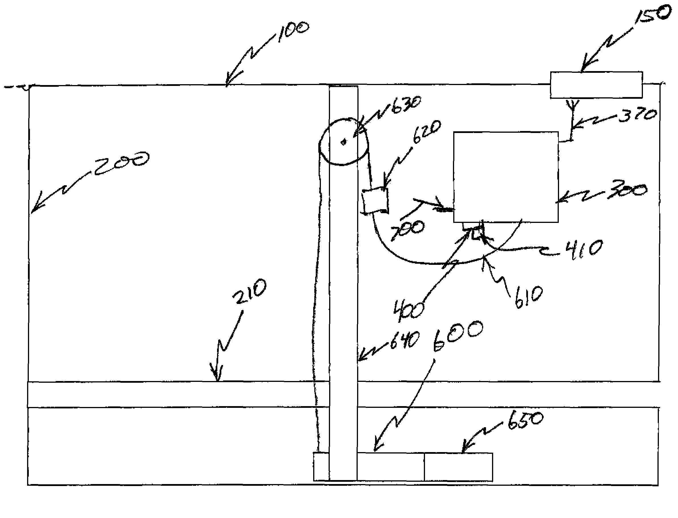
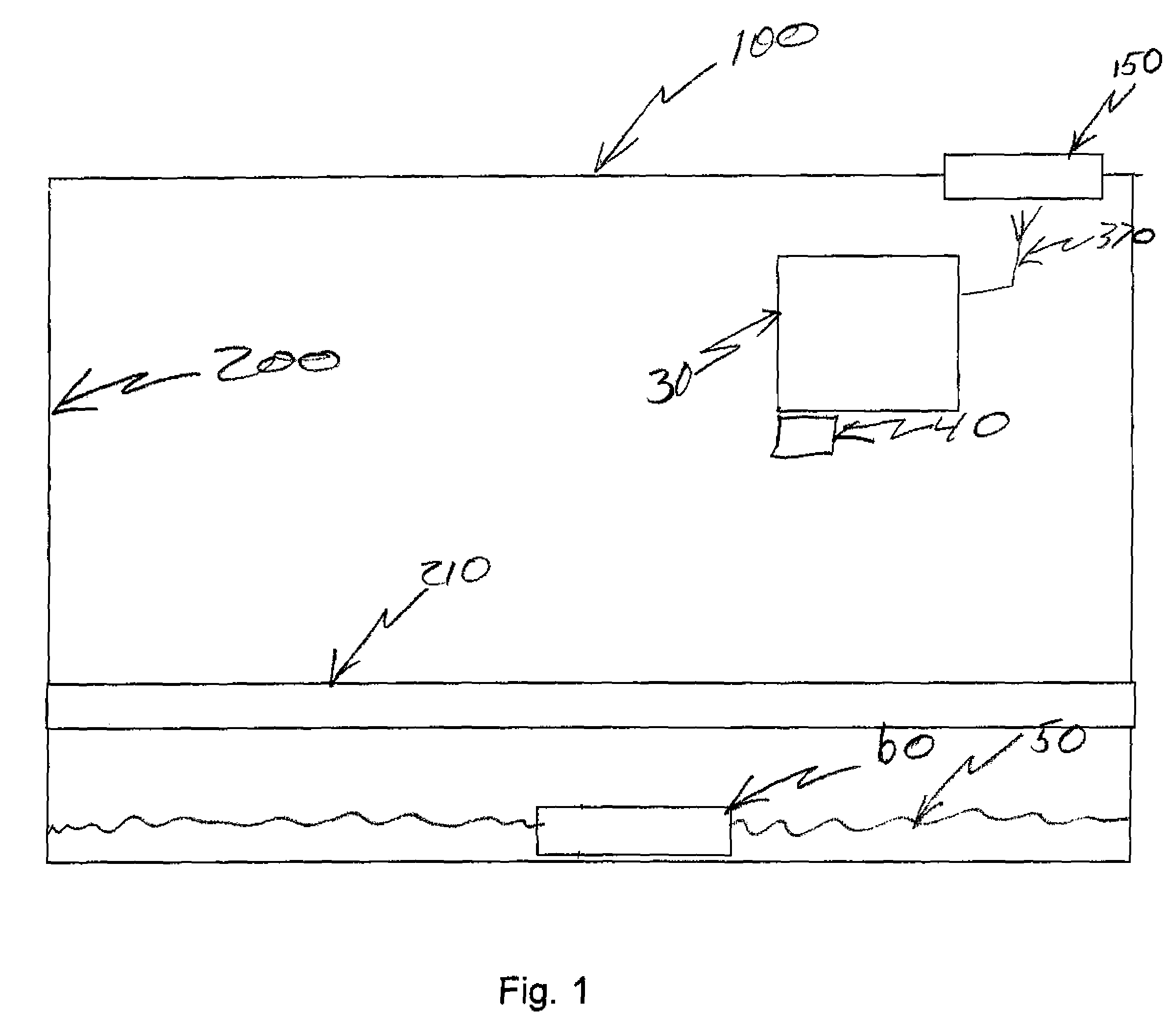
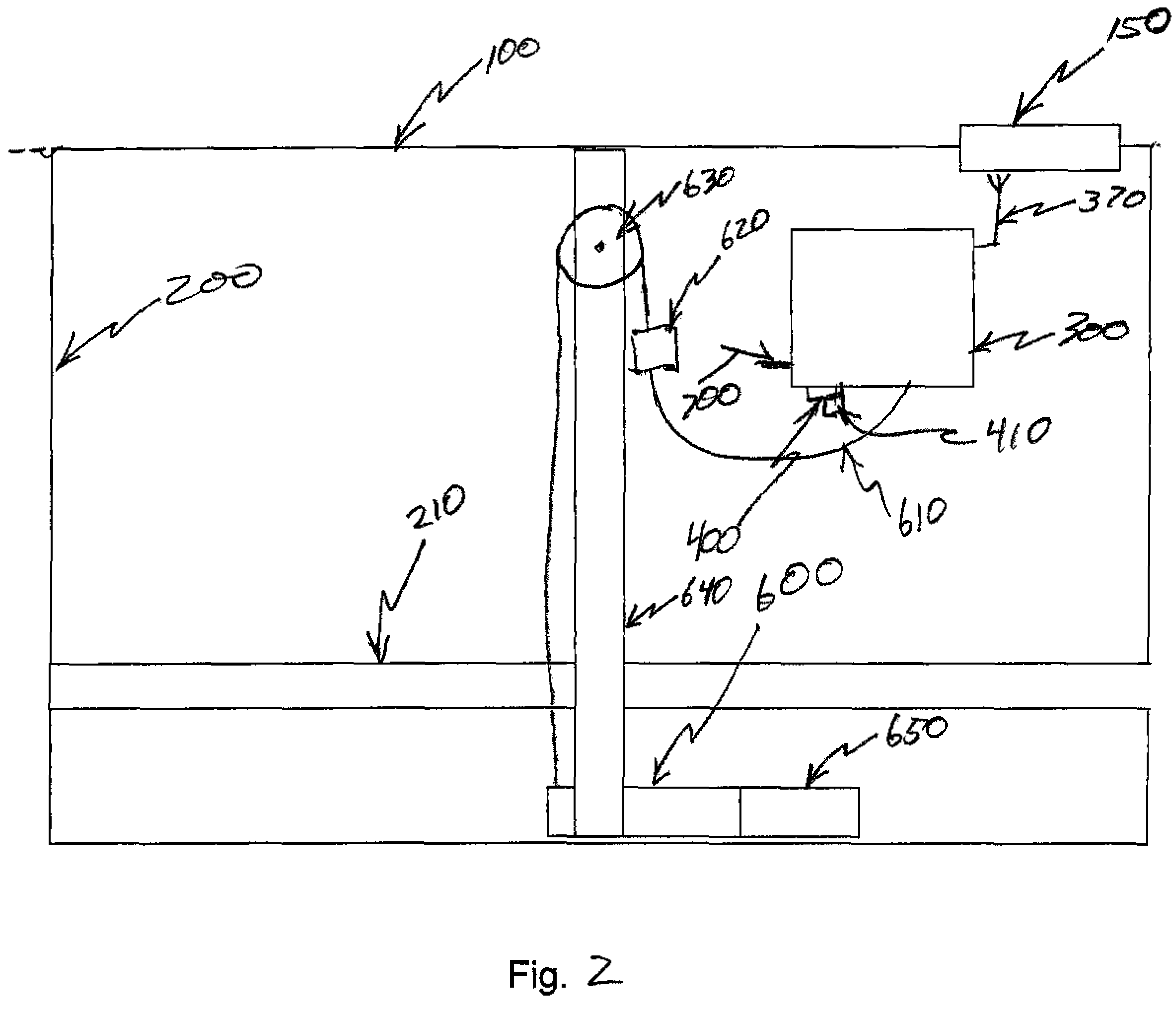
[0014]The present invention concerns a system and method for monitoring fluids inside an enclosure. More specifically the present invention relates to a utility vault or utility vault monitoring system comprising an assembly mounted at or near the ceiling of the utility vault and a floating assembly or barge that floats in the presence of water. As used herein, the term utility vault refers to a room, typically underground, providing access to subterranean utility equipment, such as valves for water or natural gas pipes, or switchgear for electrical or telecommunications equipment. A utility vault is commonly constructed out of reinforced concrete, poured cement or brick. Small utility vaults are typically entered through a manhole or grate on the topside. Larger utility vaults are often similar to mechanical or electrical rooms in design and content.

[0015]Referring to the drawings, like numbers indicate like parts throughout the views as used in the description he...


PUM


Abstract

A fluid monitoring apparatus and method is disclosed for use in an underground utility vault. Specifically, a system utilizing multiple sensors to determine the total amount and type of fluid present in a utility vault is disclosed. A first sensor located above the fluid detects and determines the overall depth of fluid present. A second sensor, relying on specific properties of the fluid(s) present, is located in contact with the fluids present. The information regarding specific fluid level and type is conveyed to a central location for monitoring.

Description

FIELD OF THE INVENTION[0001]This invention relates to a system for measuring and detecting the presence of one or more fluids in an enclosed space and for transmitting that information. More specifically, the invention is directed to a system and apparatus for measuring the presence of water and dielectric fluid inside an enclosure such as a utility vault and transmitting that information to a remote location.BACKGROUND OF THE INVENTION[0002]Underground electrical distribution systems, such as those located in urban areas and under streets utilize underground utility vaults or enclosures to install utility components, such as transformers, wires, conduits etc. Exposure of these components to the elements, such as water are a constant threat and concern to providers. Additionally, the presence of certain fluids in utility vaults may indicate problems or potential problems requiring immediate attention. The traditional method of detecting and monitoring fluid in underground utility va...

Claims


Application Information

Patent Timeline
Patent Type & Authority Patents(United States)
IPC IPC(8): G01F23/26
CPCG01F23/246G01F23/268G01F23/284G01F23/292G01F23/2962G01F23/683G01F23/76H02G9/10
Inventor BLENDINGER, LAWRENCERYAN, ROBERT M.
Owner WALKER ENG
Why Eureka
Try Eureka