Systems and methods for mitigating a blast wave

Active Publication Date: 2011-02-01
RAYTHEON CO
View PDF27 Cites 15 Cited by
  • Summary
  • Abstract
  • Description
  • Claims
  • Application Information

AI Technical Summary

Benefits of technology

[0004]In accordance with a particular embodiment of the present disclosure, a method to mitigate a blast wave includes detecting an imminent explosion that pro

Problems solved by technology

Explosions are dangerous not only because of the shrapnel that may be thrown from the explosion, but also because of the blast wave an explosion generates.
The more powerful the explosion the more damaging the blast wave.
Blast waves may damage equipment and harm individuals because of the severe pressure differentials that are experienced over an extremel

Method used


Image

  • Systems and methods for mitigating a blast wave
  • Systems and methods for mitigating a blast wave
  • Systems and methods for mitigating a blast wave

Examples


Example

[0016]Particular embodiments of the disclosure and their advantages are best understood by reference to FIGS. 1-4.

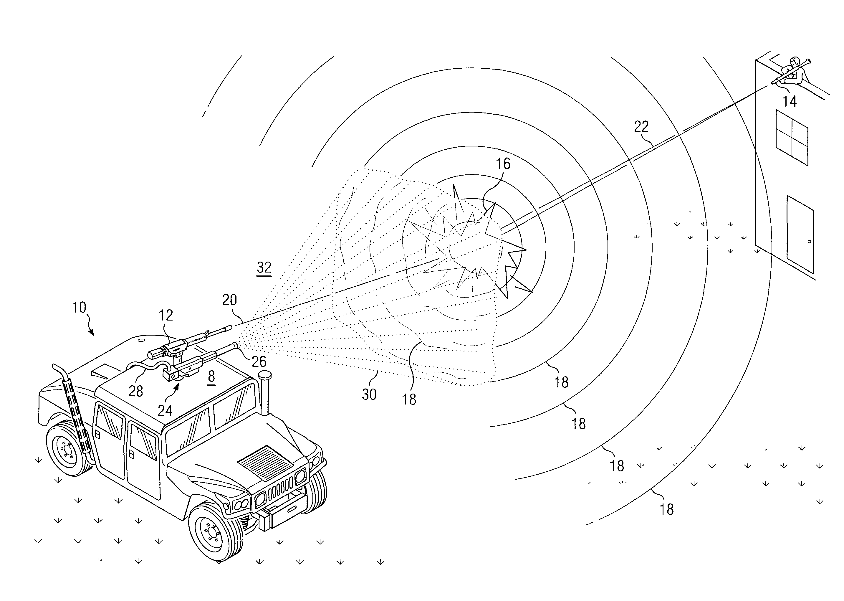
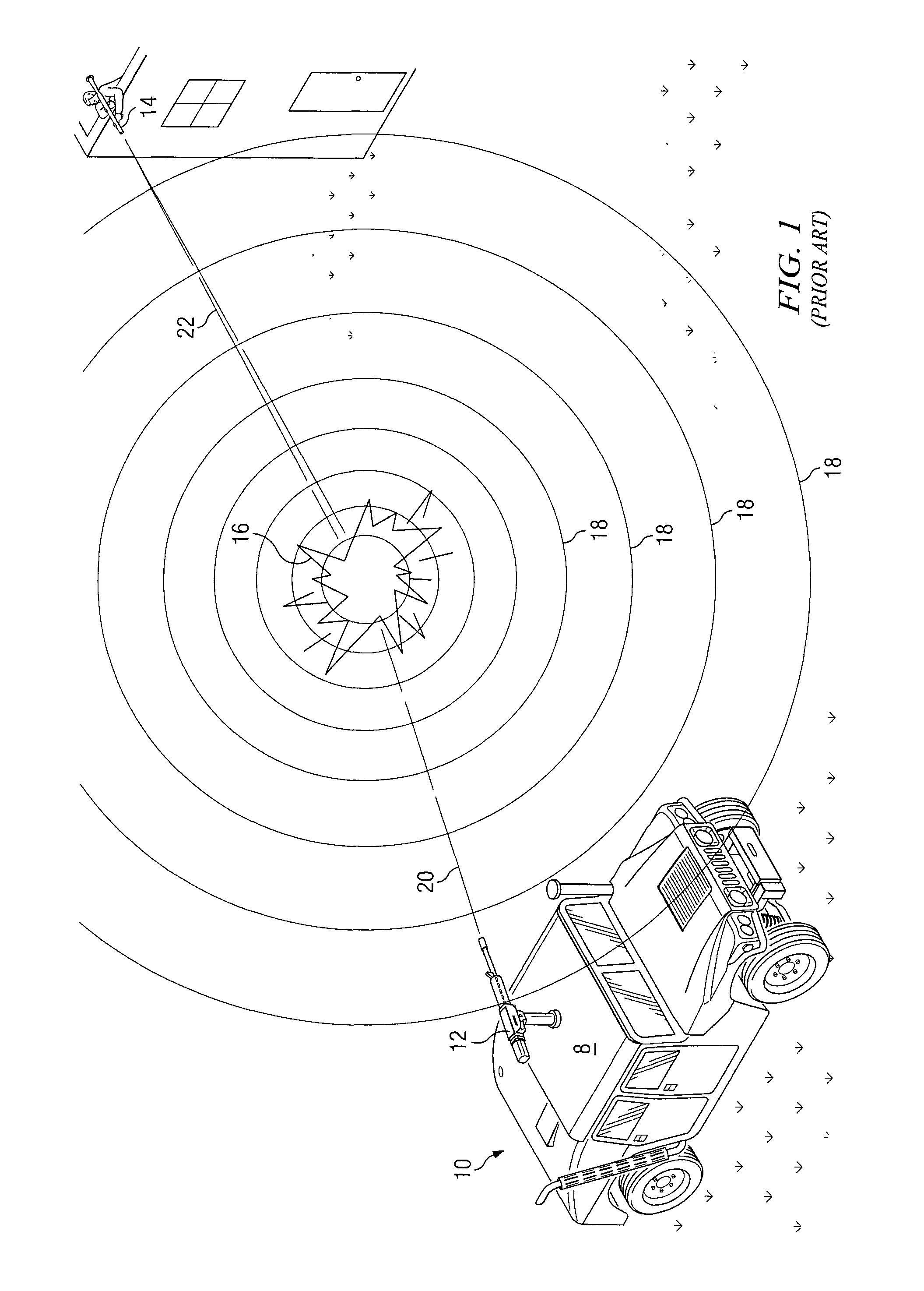
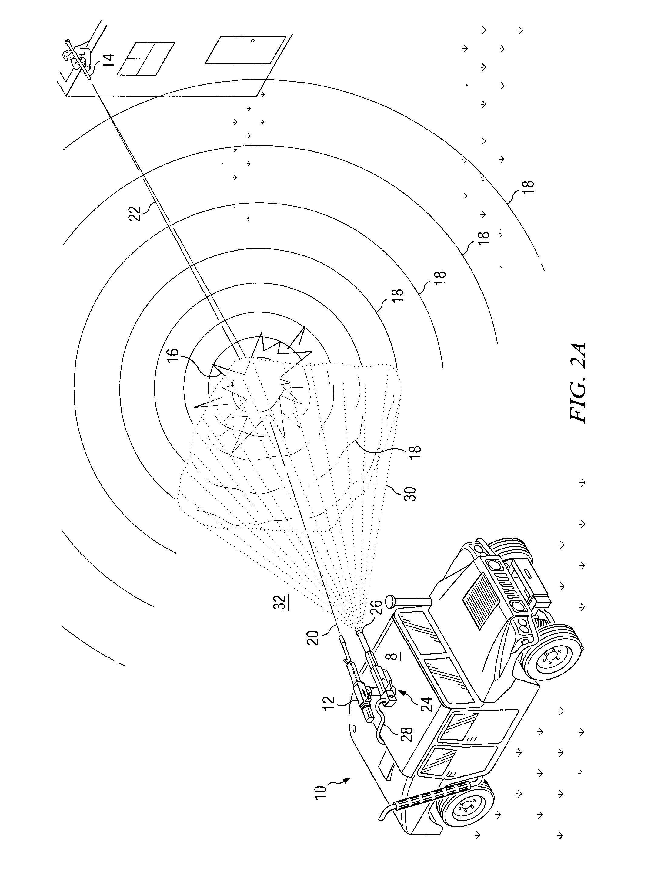
[0017]FIG. 1 illustrates a scene that may be observed on a battlefield. Vehicle 8 may be a target of an individual with a rocket propelled grenade launcher (“RPG”) 14. Active Protection System (“APS”) 10 may protect vehicle 8 from the grenade launched by RPG 14. Active Protection System 10 may include a rocket launcher 12. Upon detection of the incoming grenade by APS 10, rocket launcher 12 may launch a small rocket towards the incoming grenade launched from RPG 14. The rocket may travel along rocket path 20 and intercept the grenade traveling along grenade path 22 at a relatively safe distance from vehicle 8. When the rocket launched from APS 12 hits the grenade launched from RPG 14 an explosion 16 may be created. Explosion 16 may occur approximately meters, for example, away from vehicle 8. It may destroy the grenade and provide some protection for vehicle 8 and its oc...


PUM


Abstract

In accordance with a particular embodiment of the present disclosure, a method to mitigate a blast wave includes detecting an imminent explosion that produces a blast wave. In response to this detection, the energy of a portion of this blast wave may be reduced by deploying a fluid in the path of the blast wave.

Description

TECHNICAL FIELD[0001]The present invention relates generally to mitigating a blast wave, and in particular reducing the energy of a blast wave using a fluid.BACKGROUND[0002]Explosions are dangerous not only because of the shrapnel that may be thrown from the explosion, but also because of the blast wave an explosion generates. The more powerful the explosion the more damaging the blast wave. Blast waves may damage equipment and harm individuals because of the severe pressure differentials that are experienced over an extremely short period of time. In certain explosions, normal atmospheric pressure may rise to over 100 psi and then drop to below −20 psi in less than 2500 microseconds. Under these conditions, severe injury to ears, eyes, and lungs may result.[0003]In certain defense applications, an approximate time of detonation and location of an explosion may be known. For example, a rocket propelled grenade may be intercepted by a rocket fired from a defense system at a relativel...

Claims


Application Information

Patent Timeline
IPC IPC(8): F41H13/00
CPCF41B9/0087F41H5/007F42D5/045
Inventor IMHOLT, TIMOTHY J.ST. CLAIRE, ALEXANDER F.
Owner RAYTHEON CO
Why Eureka
Try Eureka