Locking and recocking assembly with swivel breech-lock and rotating locking head, particularly for inertially-actuated weapons using the kinetic energy of recoil

a technology of swivel breech-lock and locking head, which is applied in the direction of weapon components, cartridge extractors, weapons, etc., can solve the problems of general constructive complexity, less reliable, and high cost of the system described above, and achieve the effect of dampening the impact of the swivel breech-lock

Active Publication Date: 2011-02-01
BENELLI ARMI
View PDF4 Cites 1 Cited by
  • Summary
  • Abstract
  • Description
  • Claims
  • Application Information

AI Technical Summary

Benefits of technology

[0013]Within the scope of this aim, an object of the invention is to provide a locking and recocking assembly which provides a better balancing and stability of the weapon.
[0014]Another object of the invention is to provide a locking and recocking assembly which is constructively simple and is capable of ensuring high reliability in operation.
[0015]Another object is to provide a locking and recocking assembly which is easy to assemble and disassemble.
[0018]The swivel breech-lock in fact accommodates a rotating locking head which provides the closure and opening of the firing chamber of the weapon by way of a rotary motion determined by a helical cam provided on its shank, with the contribution of helical inclined planes which mutually converge and are formed both on the rotating closing head and on the swivel breech-lock, capable of avoiding any bouncing of the swivel breech-lock when, during locking, it abuts against the spring of the inertial system.
[0021]A damper is connected directly, by means of plates and with the aid of the recovery spring guiding pin and the ejector spring guiding pin, to the locking and recocking assembly with swivel breech-lock and rotating closing head according to the present invention. The damper dampens the impact of the swivel breech-lock against its stroke limit during opening, during which the entire assembly is always kept guided by a tab of the pivot for the rotation of the closing head, which also is mounted on the swivel breech-lock and engages a seat formed inside the sheath or barrel extension of the weapon.

Problems solved by technology

The systems described above are generally constructively complicated and expensive, less reliable due to the large number of components used, and difficult to maintain.

Method used


Image

  • Locking and recocking assembly with swivel breech-lock and rotating locking head, particularly for inertially-actuated weapons using the kinetic energy of recoil
  • Locking and recocking assembly with swivel breech-lock and rotating locking head, particularly for inertially-actuated weapons using the kinetic energy of recoil
  • Locking and recocking assembly with swivel breech-lock and rotating locking head, particularly for inertially-actuated weapons using the kinetic energy of recoil

Examples


Embodiment Construction

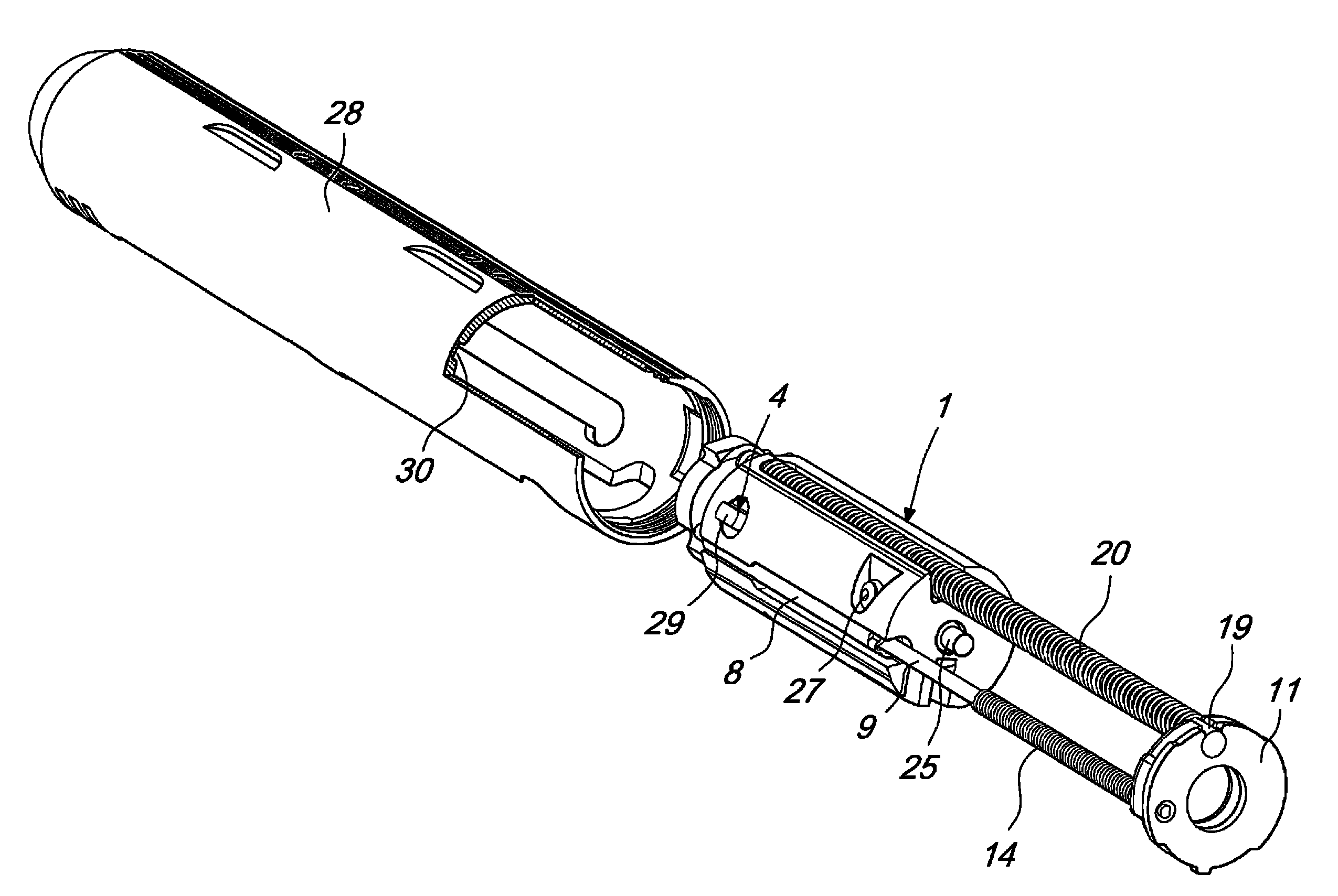
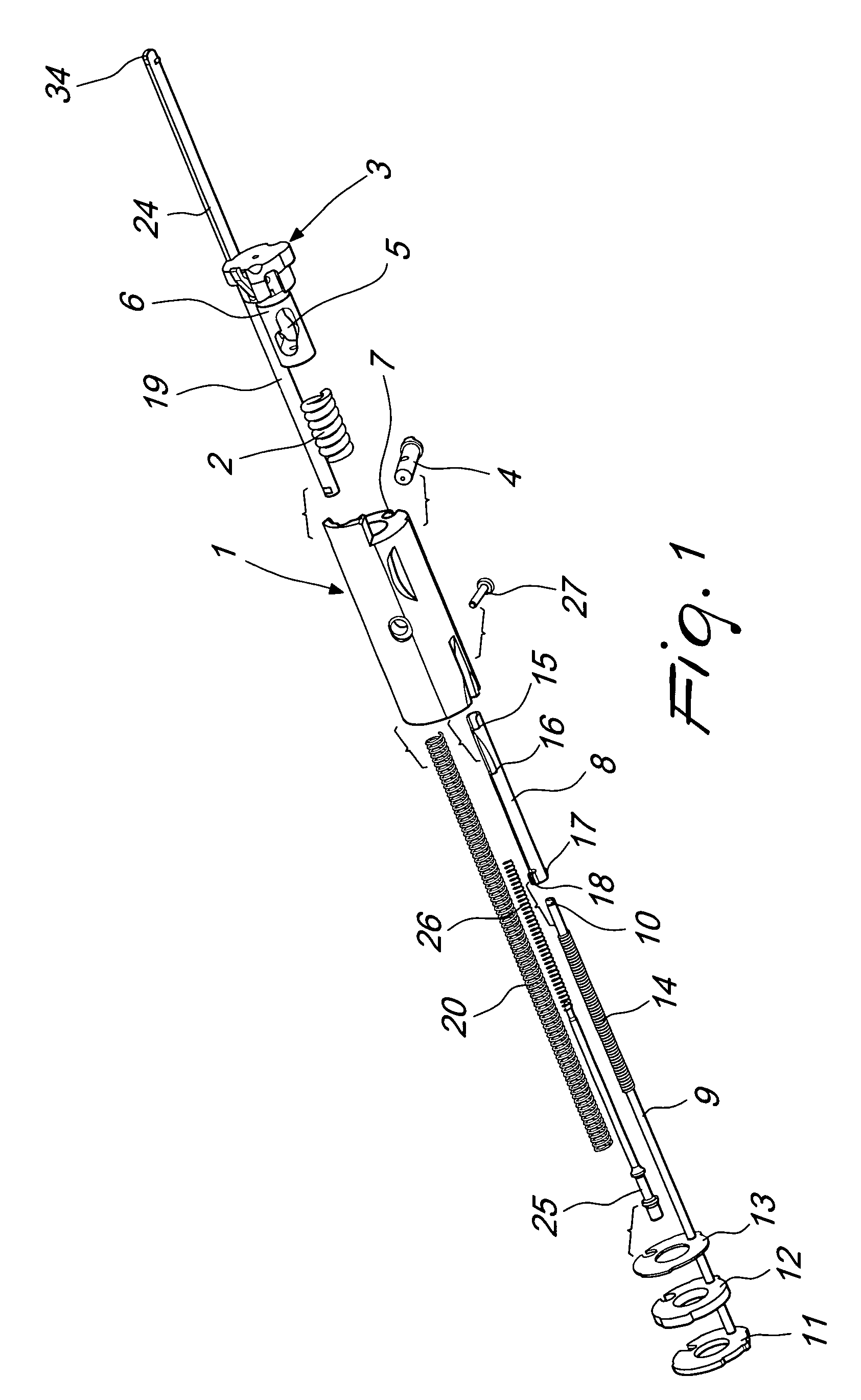
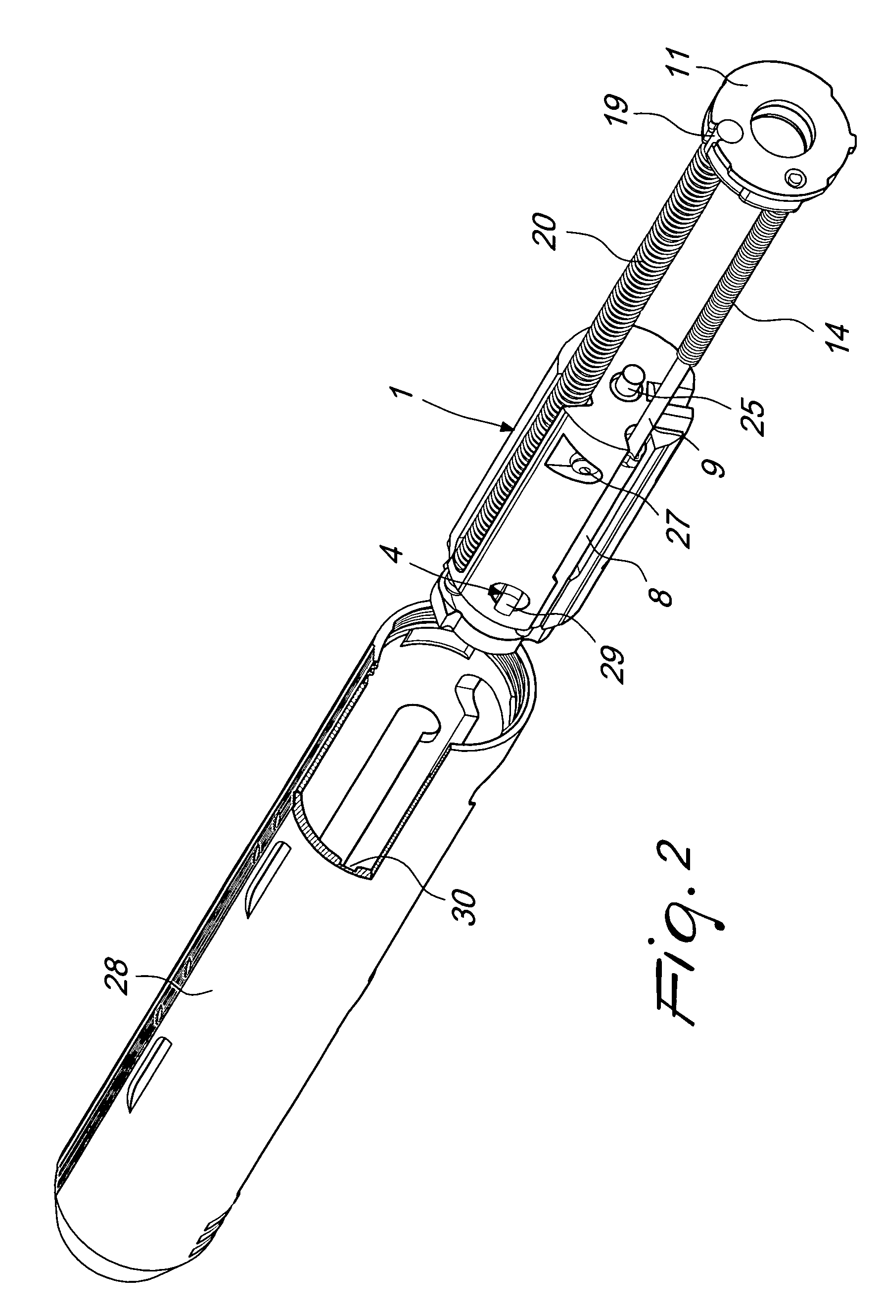
[0034]With reference to the cited figures, the locking and recocking assembly with swivel breech-lock and rotating locking head according to the invention comprises a breechblock 1 in which a breech-lock recoil spring 2 is inserted and in which a rotating locking head 3 is mounted. Inasmuch as breechblock 1 carries a rotating or swiveling locking head 3 and houses a breech-lock recoil spring 2, the term “swivel breech-lock’ is used to denote breechblock 1 herein.

[0035]The rotating locking head 3 is jointly connected to the breech-lock 1 by means of a head rotation pivot 4, which in order to concentrate all the movable mass required for the operation of the weapon on the breech-lock is jointly connected to the breech-lock and engages a helical cam 5 provided on a cylindrical shank 6 of the locking head.

[0036]This construction of the swivel breech-lock 1 minimizes the removals of material on the breechblock and allows to therefore maximize its mass.

[0037]An ejector body 8 is then inse...


PUM


Abstract

A locking and recocking assembly with swivel breech-lock and rotating locking head particularly designed for inertially-actuated weapons, which combines in a single assembly all the functions for locking, opening, case ejection and recocking with locking return, required for correct operation of the weapon; those functions were, until now assigned to various components variously assembled on the weapon. The locking and recocking assembly with swivel breech-lock and rotating locking head has the entire mass, required for inertial operation, concentrated in the swivel breech-lock, which is accommodated completely within the supporting structure of the weapon, such as the sheath or barrel extension or breech of the weapon. All this leads to better balancing and stability of the weapon, higher reliability in operation, greater constructive simplicity and ease of assembly and disassembly.

Description

BACKGROUND OF THE INVENTION[0001]1. Field of the Invention[0002]The present invention relates to a locking and recocking assembly with swivel breech-lock and rotating locking head, particularly for inertially-actuated weapons which use the kinetic energy of recoil.[0003]2. Description of the Prior Art[0004]Inertially-actuated weapons have long been known in which the recoil of the weapon is used to store energy by means of the compression of a spring which is interposed between the breech and the locking head and to exploit its elastic reaction to power the various operations of the recocking cycle: closure, opening, case extraction and expulsion, trigger arming, compression of the breech recovery spring, return to closure with insertion of the new cartridge in the barrel.[0005]All these functions are traditionally performed by various components which are mounted on the weapon in different positions in relation to the technical solution used.[0006]There are systems in which the ine...

Claims


Application Information

Patent Timeline
Patent Type & Authority Patents(United States)
IPC IPC(8): F41A3/26
CPCF41A3/26F41A3/72F41A15/14F41A15/16F41A25/12
Inventor MORETTI, LUIGI
Owner BENELLI ARMI
Why Eureka
Try Eureka