
Mitigation of unsteady peak fan blade and disc stresses in turbofan engines through the use of flow control devices to stabilize boundary layer characteristics

a technology of flow control device and turbine blade, which is applied in the direction of liquid fuel engine, vessel construction, marine propulsion, etc., to achieve the effects of reducing or eliminating unsteady aerodynamic flow effects, extending the life of the fan blade, and reducing the stress and resonance level of the blade and dis

Active Publication Date: 2011-02-01
ROLLS ROYCE DEUT LTD & CO KG
View PDF41 Cites 25 Cited by
  • Summary
  • Abstract
  • Description
  • Claims
  • Application Information

AI Technical Summary

Benefits of technology

[0015]Compared to the heretofore described traditional methods, this invention provides a more direct, powerful and efficient tool to reduce or eliminate unsteady aerodynamic flow effects existing on turbofan fan or compressor blades. Implementation ensures reduced blade and disc stresses and resonance levels during flight operations thereby extending fan blade life through the avoidance of at least blade and disc cracking and the subsequent catastrophic structural failure of the disc assembly. Among other benefits, the invention is easy and cost effective to implement; is extremely effective and efficient in reducing fan blade and disc stresses; and the prescribed adaptations and / or devices are passive in nature, and once installed, require substantially no attention or monitoring.
[0016]As described above, a primary purpose of this invention is the stabilization and strategic positioning of the transition point between laminar and turbulent flow on an operating turbofan fan blade. The invention utilizes features that initiate boundary layer transition at a specific location on the turbofan fan blade, thereby eliminating the previously experienced detrimental stresses imposed upon the untreated turbofan assembly.

Problems solved by technology

However, the physical structures by which such a feature is fabricated and / or implemented on the fan blade is of secondary importance to the innovation of utilizing the feature in the described environment of a fan blade, and has heretofore been unknown.

Method used


Image

  • Mitigation of unsteady peak fan blade and disc stresses in turbofan engines through the use of flow control devices to stabilize boundary layer characteristics
  • Mitigation of unsteady peak fan blade and disc stresses in turbofan engines through the use of flow control devices to stabilize boundary layer characteristics
  • Mitigation of unsteady peak fan blade and disc stresses in turbofan engines through the use of flow control devices to stabilize boundary layer characteristics

Examples


Embodiment Construction

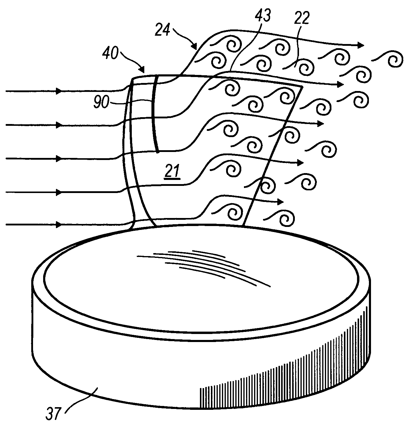
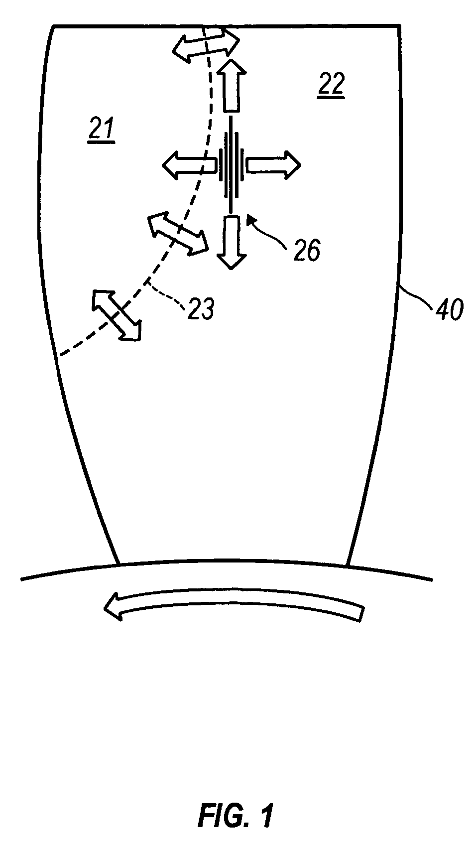
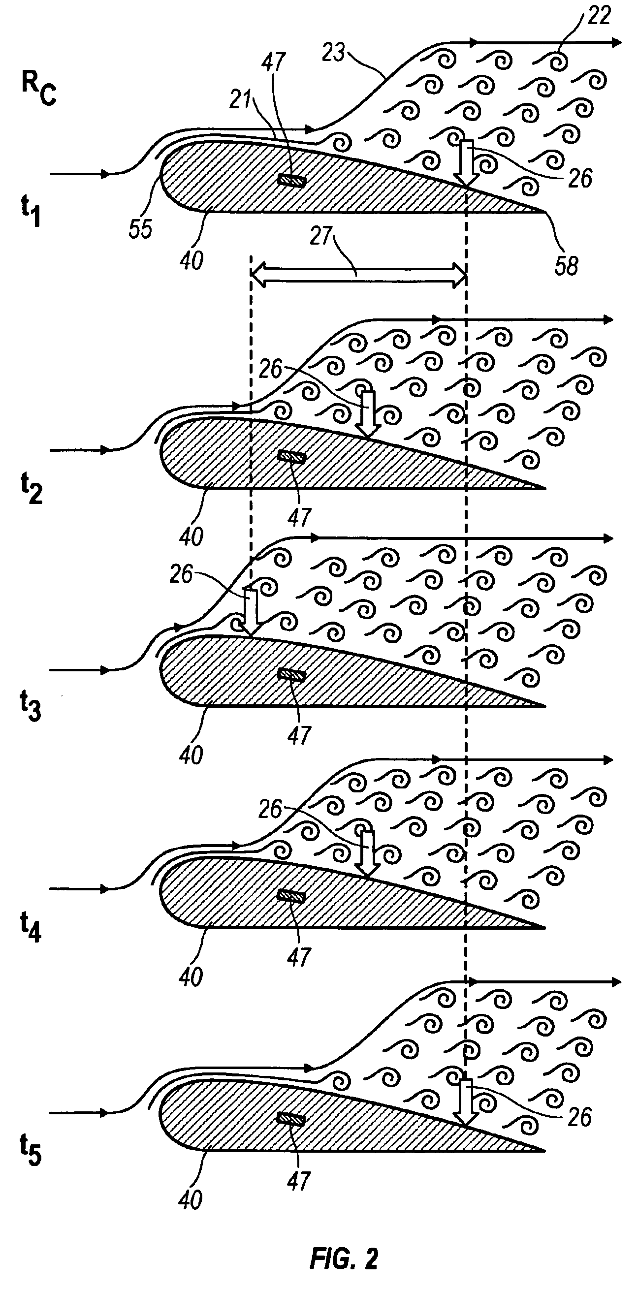
[0034]In the description below and the accompanying drawings, various aspects of treated and untreated turbofan blades, and their incorporating structures, are described and illustrated. In that regard, the following reference numerals have been utilized to designate these features.[0035]jet aircraft[0036]region of laminar flow[0037]region of turbulent flow[0038]unstable laminar to turbulent boundary layer transition zone[0039]positionally stabilized boundary layer transition[0040]positionally steady aerodynamic force[0041]positionally unsteady aerodynamic force[0042]range of movement of unsteady aerodynamic load[0043]distance from leading edge of fan blade[0044]turbofan based power unit[0045]turbofan assembly[0046]fan disc[0047]turbofan blade[0048]fan blade tip[0049]chord length[0050]torsional axis of turbofan blade[0051]high-pressure side of turbofan fan blade[0052]low-pressure side of turbofan fan blade[0053]leading edge of fan blade[0054]trailing edge of fan blade[0055]essential...


PUM


Abstract

Method and apparatus for providing a turbofan blade 40 adapted to initiate and control a boundary layer transition at a side surface of the blade 40 during operation as a component in a turbofan assembly 35. The turbofan blade 40 includes a leading edge 55, a trailing edge 58, and two side surfaces including a high-pressure side surface 49 and a low-pressure side surface 52. At least one of the two side surfaces has an essentially smooth surface portion 61 located between the leading and trailing edges, and the essentially smooth surface portion is interrupted by a surface deviation 64. The surface deviation is configured to fix a positionally unstable laminar to turbulent boundary layer transition 24 at a location toward the trailing edge from the surface deviation during operation of the turbofan blade in the turbofan assembly. In this manner, fatigue inducing and / or structurally damaging unsteady aerodynamic forces experienced upon the blade and / or fan disc during operation are controlled, and the resultant fluctuating fan blade and disc peak stresses are mitigated.

Description

CROSS-REFERENCE TO RELATED PATENT APPLICATIONS[0001]The present application claims the benefit of U.S. Provisional Application Nos. 60 / 481,820 filed 20, Dec. 2003 and 60 / 481,889 filed 13, Jan. 2004. The present application is also a continuation of International Patent Application No. PCT / US2004 / 009897 filed 26, Mar. 2004 which was published in English pursuant to Article 21(2) of the Patent Cooperation Treaty; all of said applications, in their entireties, being hereby expressly incorporated by reference into the present application.TECHNICAL FIELD[0002]This invention provides a method to mitigate the peak fluctuating stresses in turbofan fan blades and / or fan discs, a task accomplished through the control of fatigue inducing and / or structurally damaging unsteady aerodynamic forces that develop when a positionally unstable transition from a laminar to turbulent boundary layer exists on an untreated fan blade. Stabilized transition from a laminar to turbulent boundary layer is achie...

Claims


Application Information

Patent Timeline
Patent Type & Authority Patents(United States)
IPC IPC(8): F01D5/14F04D29/38F04D29/66F04D29/68F15D1/12
CPCF01D5/145F04D29/384F04D29/668F04D29/681F15D1/12Y02T50/673F05D2240/31F04D29/324Y02T50/60
Inventor MILLS, ROBERT J.HENNE, PRESTON A.
Owner ROLLS ROYCE DEUT LTD & CO KG
Learn More