Quantum key distribution system and method

a distribution system and quantum key technology, applied in the direction of digital transmission, unauthorized memory use protection, instruments, etc., can solve the problems of quantum state loss, large size and weight, and relatively complex hardware of the qkd system, so as to reduce the quantum bit error rate

Active Publication Date: 2011-02-01
THE BOEING CO
View PDF6 Cites 15 Cited by
  • Summary
  • Abstract
  • Description
  • Claims
  • Application Information

AI Technical Summary

Benefits of technology

[0018]A further embodiment of the disclosure provides a method and system for reducing quantum bit error rate in a quantum key distribution system. The method includes transmitting a quantum key signal from a transmitter at a first timing, and detecting the transmitted quantum key signal by a detector at a receiver. An output signal of the detector is sampled at a second timing that is delayed relative to the first timing.
[0020]A further embodiment of the disclosure provides a method for reducing quantum bit error rate in a free space quantum key distribution system. The method includes transmitting a quantum key signal from a transmitter across free space to a receiver at a first timing, and detecting the transmitted quantum key signal by a single photon detector at the receiver. An output signal of the single photon detector is sampled at a second timing that is delayed relative to the first timing.

Problems solved by technology

This results in the need for a QKD system that has relatively complex hardware, increased environmental sensitivity and that is of substantial size and weight.
Also, in a free space QKD system, quantum states are prone to be lost due to factors such as transmission losses, de-coherence, and interruptions from a potential eavesdropper.
Such a photon source, however, is fairly complicated and contributes to providing a relatively complex QKD system.
The length of the tail, in fact, may be longer than the sampling period of the SPD with the result being that the SPD may detect the photon emitted at the tail and produce an erroneous output signal.
Such detection errors can result in the QKD system having an unacceptably high QBER.

Method used


Image

  • Quantum key distribution system and method
  • Quantum key distribution system and method
  • Quantum key distribution system and method

Examples


Embodiment Construction

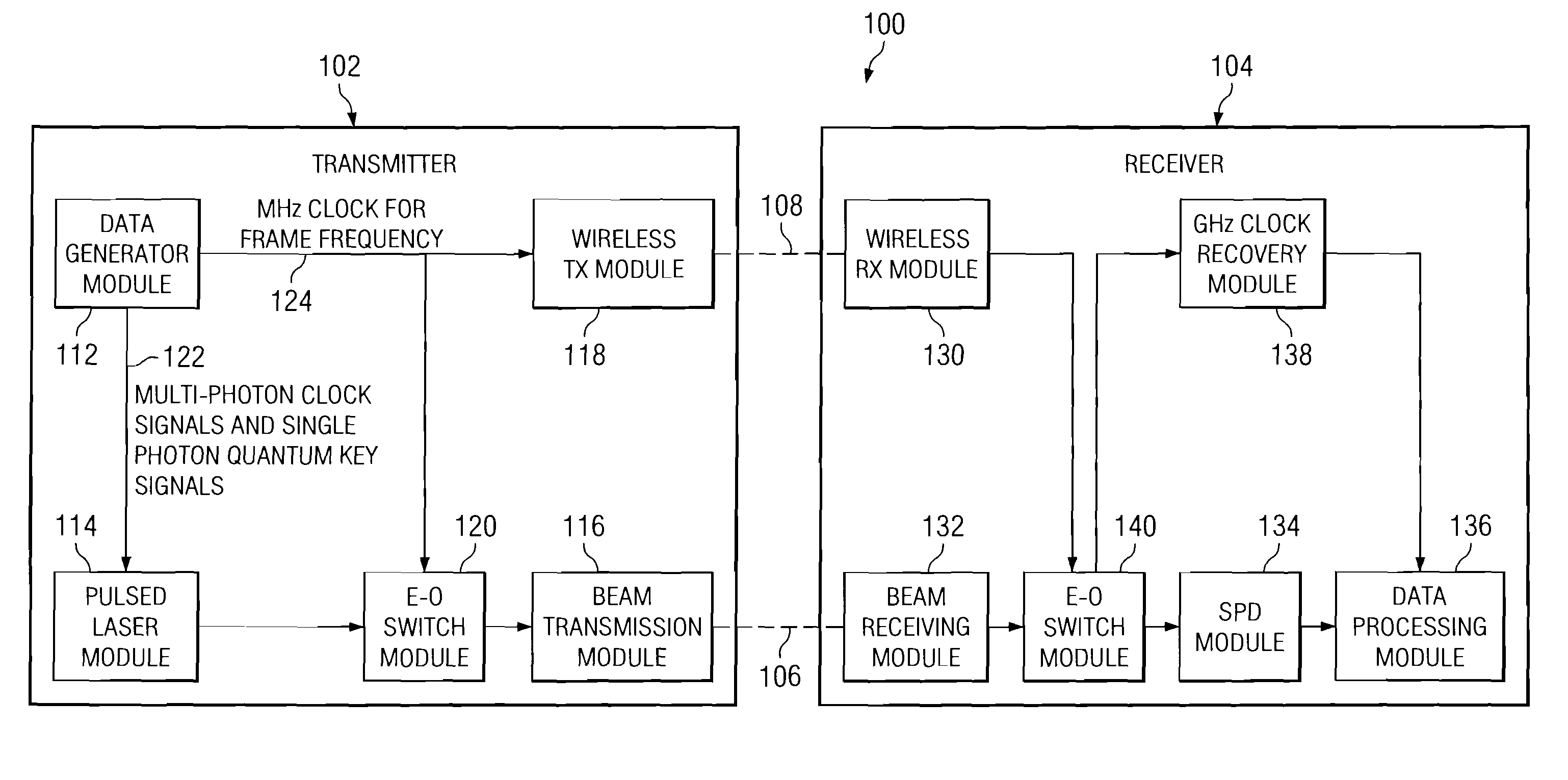
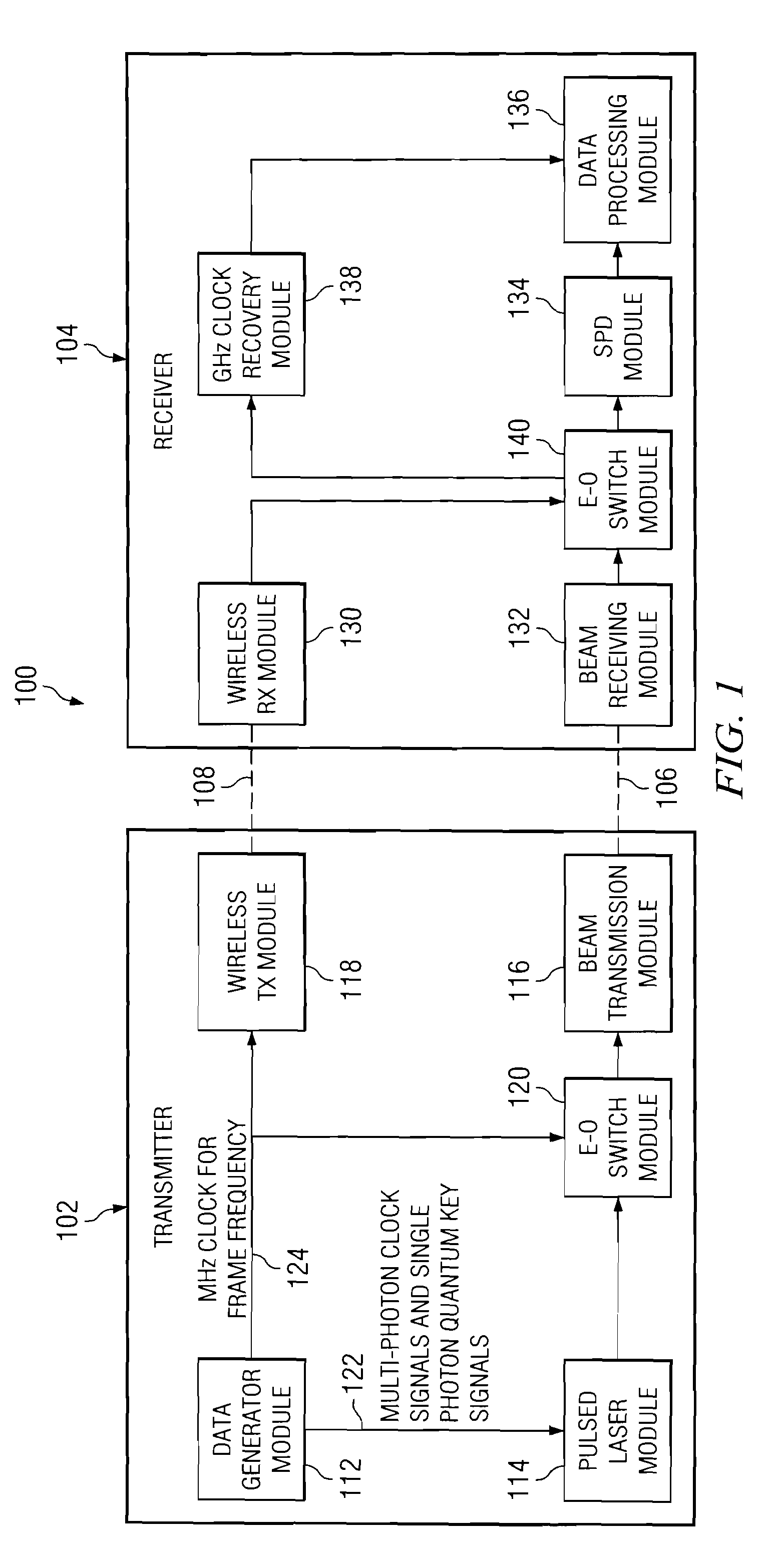
[0036]With reference now to the figures, and, in particular, with reference to FIG. 1, an illustration of a free space quantum key distribution system in accordance with an advantageous embodiment of the disclosure is depicted. The free space quantum key distribution (QKD) system is designated by reference number 100, and may include transmitter 102 and receiver 104 capable of optically communicating with one another across free space via a single optical channel schematically illustrated at 106, and via a wireless communications link schematically illustrated at 108.

[0037]Transmitter 102 may include data generator module 112, pulsed laser module 114, beam transmission module 116, wireless transmitter module 118 and electro-optic (E-O) switch module 120. Data generator module 112 produces random bits (raw keys). The random bits may be generated, for example, by a pseudo-random number generator or by a real quantum random number generator. A pseudo-random number generator is based on...


PUM


Abstract

Method and system for transmitting optical clock signals and quantum key signals on a single optical channel. A multi-photon optical clock signal is received at an electro-optic switch at a first clock rate. The electro-optic switch may be configured for an interval defined by a second clock rate for generating a single photon quantum key signal. The multi-photon optical clock signal and the single photon quantum key signal are combined such that the single optical channel transmits the single photon quantum key signal at a first interval and the multi-photon optical clock signal at a second interval. The quantum key signal is transmitted from a transmitter at a first timing, and detected by a detector at a receiver. An output signal of the detector is sampled at a second timing that is delayed relative to the first timing for reducing quantum bit error rate.

Description

BACKGROUND INFORMATION[0001]1. Field[0002]The disclosure relates generally to a quantum key distribution system and, more particularly, to a method and system for transmitting optical clock signals and quantum key signals on a single optical channel in a free space quantum key distribution system, and for reducing quantum bit error rate in a free space quantum key distribution system.[0003]2. Background[0004]Quantum Key Distribution (QKD), which was first recognized in the early 1990s as a means to produce a random bit stream for encryption, has recently seen increased interest from both military and civil spheres as providing information assurance, creating a secure communications environment. In a QKD system, lasers are used to generate quantum mechanically coupled photon states. The nature of this coupling allows the photons to simultaneously exist in orthogonal modes. These orthogonal modes are typically manifested in optical polarization, with orthogonal modes being vertical an...

Claims


Application Information

Patent Timeline
Patent Type & Authority Patents(United States)
IPC IPC(8): H04L9/00H04L29/06H04L9/28H04L9/32G06F12/14
CPCH04L9/0852H04L9/12H04L2209/80
Inventor WANG, SHUOQINZEHNDER, DANIEL M.HUNT, JEFFREY H.
Owner THE BOEING CO
Why Eureka
Try Eureka