Acceleration measuring device

a technology of acceleration measurement and measuring device, which is applied in the direction of speed/acceleration/shock measurement device, speed/acceleration/shock measurement device, instrument, etc., can solve the problems of difficult to obtain acceleration data at the stationary state, disadvantages of conventional acceleration measuring device, and long time consumption, etc., to achieve the effect of quick estimate of offset or

Active Publication Date: 2011-02-01
ASAHI KASEI ELECTRONICS CO LTD
View PDF15 Cites 2 Cited by
  • Summary
  • Abstract
  • Description
  • Claims
  • Application Information

AI Technical Summary

Benefits of technology

[0050]Therefore, an object of the present invention is to provide an acceleration measuring device that quickly obtains offsets or both of offsets and sensitivities necessary for output correction for a bi-axial or tri-axial acceleration sensor by repeatedly obtaining output data of the bi-axial or tri-axial acceleration sensor without setting attitudes of the acceleration measuring device in a specific direction.
[0053]The reference point estimating means may define an ellipse on the two dimensional orthogonal coordinate plane or an ellipsoidal surface on the three dimensional orthogonal coordinate space based on both the distribution of a group of two-axis or three-axis acceleration data obtained by the acceleration data obtaining means on the two dimensional orthogonal coordinate plane or the three dimensional orthogonal coordinate space and the importance group calculated by the importance calculating means pertaining to the acceleration data group. The reference point estimating means may estimate a coordinate of center point and radiuses of respective principal axes of the ellipse or the ellipsoidal surface, set the estimated coordinate of center point as the reference point, and set the radiuses of the respective principal axes as the scale reference of the respective axes. The offset correcting means may correct offsets and sensitivities of the respective two-axis or three-axis acceleration data based on the reference point and the scale reference of the respective axes estimated by the reference point estimating means.
[0057]The reference point estimating means may define an ellipse or an ellipsoidal surface on the two dimensional orthogonal coordinate plane or the three dimensional orthogonal coordinate space based on both a distribution on the two dimensional orthogonal coordinate plane or the three dimensional orthogonal coordinate space in a group of a predetermined number N of representative datas accumulated by the accumulating means and a group of a predetermined number N of second importance calculated by the second importance calculating means according to the representative datas, estimate a coordinate of center point and radiuses of respective principal axes of the ellipse or the ellipsoidal surface, set the estimated coordinate of center point as the reference point, set the radiuses of the respective principal axes as the scale reference. The offset correcting means may correct offsets and sensitivities of the respective two-axis or three-axis acceleration data based on the reference point and the scale reference of the respective axes estimated by the reference point estimating means.
[0067]According to the present invention, a reference point defined on a two dimensional orthogonal coordinate plane or a three dimensional orthogonal coordinate space and scale reference of respective axes are estimated based on both a distribution on the two dimensional orthogonal coordinate plane or the three dimensional orthogonal coordinate space when respective axial components of the group of acceleration data including plural two-axis or three-axis acceleration data are set as coordinate values and a importance group pertaining to the acceleration data group. The acceleration data are corrected based on the estimated reference point and the scale reference of the respective axes. It is possible to repeatedly obtain output data of the bi-axial or tri-axial acceleration sensor without being careful to set attitudes of the acceleration measuring device in specific directions. Thus, offsets or both offsets and sensitivities necessary for output correction for a bi-axial or tri-axial acceleration sensor can be quickly estimated.
[0068]According to the present invention, a representative data of an obtained group of a predetermined number M of acceleration data is calculated, first importance of the representative data is calculated, the representative data is selected in the case where the representative data is with in appropriate range, the selected representative data and the first importance and additional information (time, temperature, etc.) according to the representative data are accumulated, second importance according to the representative data is calculated based on the first importance and additional information according to the accumulated representative data. A reference point defined on a two dimensional or three dimensional orthogonal coordinate space and scale reference of respective axes are estimated based on both a distribution on the two dimensional orthogonal coordinate plane or the three dimensional orthogonal coordinate space when respective axial components of the accumulated predetermined number N representative datas are set as coordinate values and a predetermined number N of second importance according to the representative datas. Therefore, it is possible to quickly estimate offsets or both of offsets and sensitivities even when temperature is altered and offsets are clearly changed.

Problems solved by technology

However, this type of conventional acceleration measuring device has disadvantages described below.
1) When a user normally operates the acceleration measuring device, in general, it is difficult to obtain acceleration data at the stationary state.
Then it takes long time.

Method used


Image

  • Acceleration measuring device
  • Acceleration measuring device
  • Acceleration measuring device

Examples


first embodiment

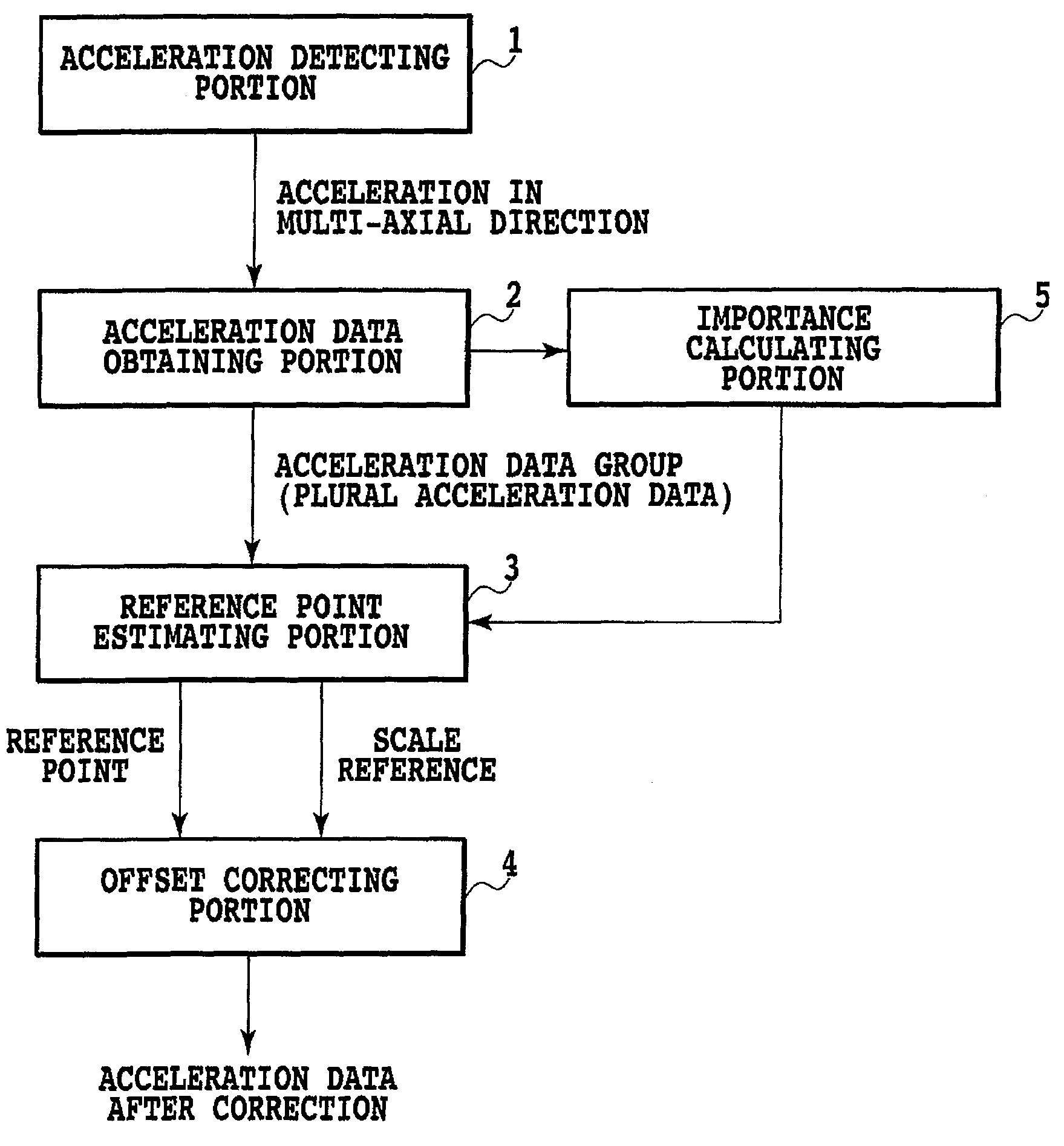
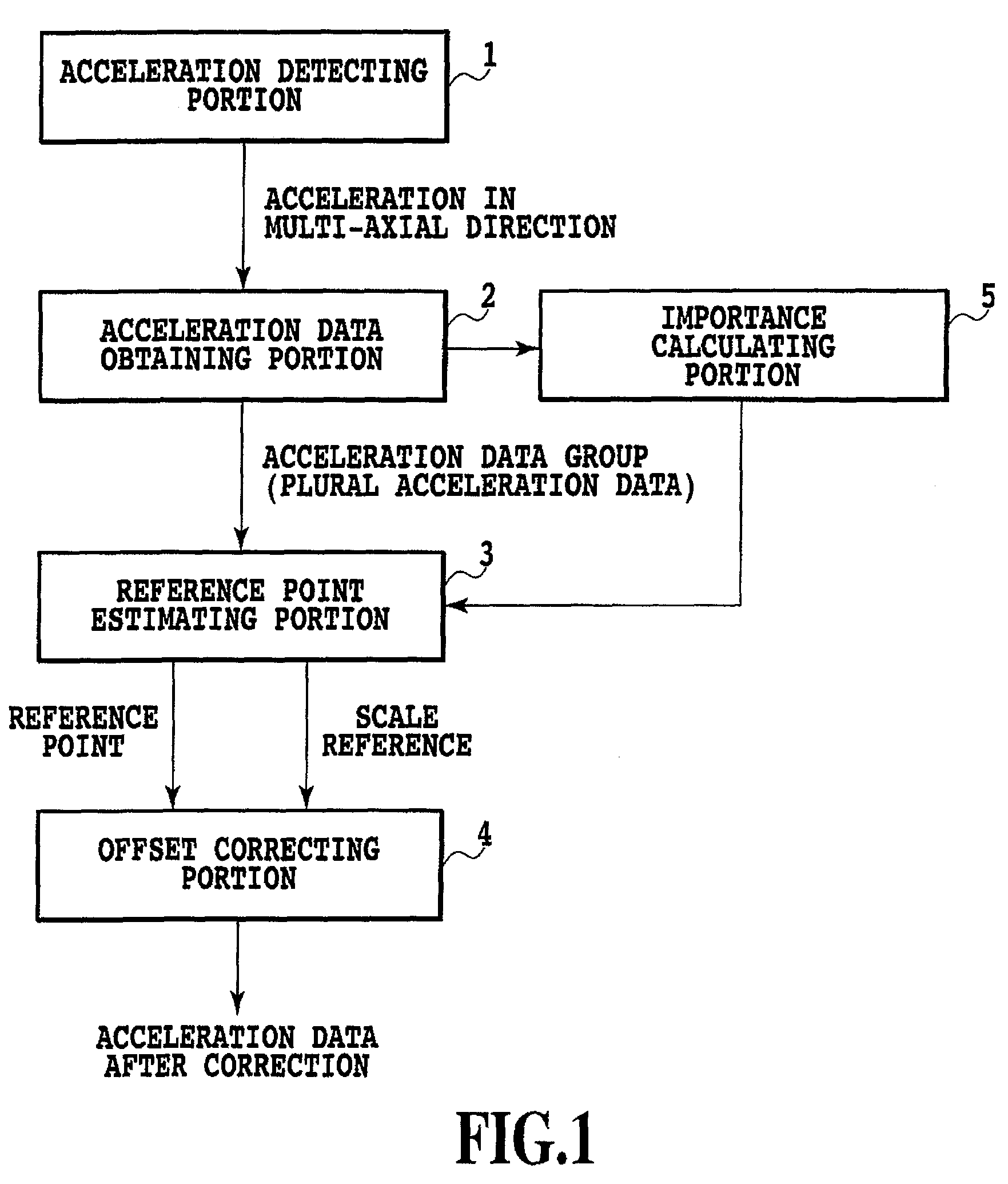
[0082]A first embodiment of the present invention is explained on the basis of FIG. 1.

[0083]Before explaining an acceleration measuring device according to the present invention in detail, in this embodiment, the basic structure of the acceleration measuring device is schematically explained.

[0084]

[0085]FIG. 1 shows the rough structure of the acceleration measuring device according to the present invention.

[0086]The acceleration measuring device includes an acceleration detecting portion 1, an acceleration data obtaining portion 2, an importance calculating portion 5, a reference point estimating portion 3, and an offset correcting portion 4.

[0087]

[0088]Basic operations of the acceleration measuring device are explained.

[0089]The acceleration detecting portion 1 detects accelerations in two-axis or three-axis directions.

[0090]The acceleration data obtaining portion 2 obtains the accelerations detected by the acceleration detecting portion 1 as acceleration data.

[0091]The reference p...

second embodiment

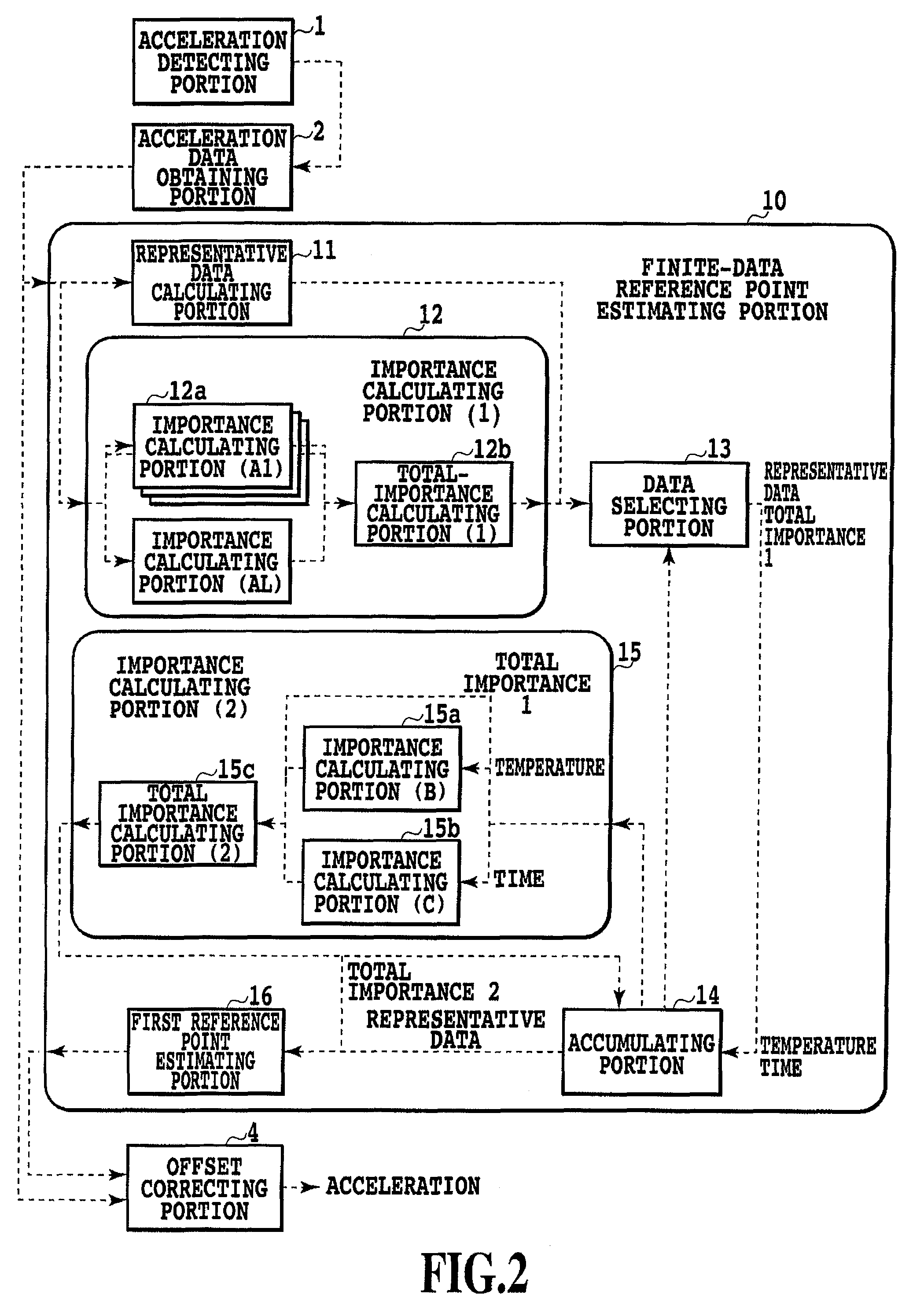
[0102]A second embodiment of the present invention is explained on the basis of FIGS. 2 to 4. Explanation of components same as those in the first embodiment is omitted and the components are denoted by the same reference numerals and signs.

[0103](Finite Data DOE)

[0104]

[0105]FIG. 2 shows an example of the structure of an acceleration measuring device according to the present invention.

[0106]The acceleration measuring device includes the acceleration detecting portion 1, the acceleration data obtaining portion 2, a finite data reference point estimating portion 10, and the offset correcting portion 4. In the following explanation, explanation concerning the components other than the finite data reference point estimating portion 10 is omitted.

[0107]The finite data reference point estimating portion 10 is explained.

[0108]The finite data reference point estimating portion 10 includes a representative data calculating portion 11, a first importance calculating portion 12, a data selecti...

third embodiment

[0192]A third embodiment of the present invention is explained on the basis of FIG. 5. Explanation of components same as those in the respective embodiments described above is omitted and the components are denoted by the same reference numerals and signs.

[0193](Infinite DOE)

[0194]

[0195]FIG. 5 shows an example of the structure of an acceleration measuring device according to the present invention.

[0196]The acceleration measuring device includes the acceleration detecting portion 1, the acceleration data obtaining portion 2, an infinite data reference point estimating portion 20, and the offset correcting portion 4. In the following explanation, explanation of the components other than the infinite data reference point estimating portion 20 is omitted.

[0197]The infinite data reference point estimating portion 20 is explained.

[0198]The infinite data reference point estimating portion 20 includes an importance calculating portion 21, a storing portion 22, and a second reference point e...


PUM


Abstract

A reference point defined on a two dimensional or three dimensional orthogonal coordinate space and scale reference of respective axes are estimated based on a distribution on the three dimensional orthogonal coordinate space at the time when respective axial components of an acceleration data group comprised of plural acceleration data including multi-axial components and a importance group pertaining to the acceleration data group, and the respective acceleration data are corrected based on the estimated reference point and scale reference of the respective axes.

Description

CROSS-REFERENCE TO RELATED APPLICATIONS[0001]This Application is the U.S. national stage under 35 U.S.C. §371 of International Application No. PCT / JP2006 / 326015, filed on Dec. 27, 2006, and claims priority to JP 2006-000721, filed Jan. 5, 2006. All of the applications are incorporated herein by reference in their entirety.TECHNICAL FIELD[0002]The present invention relates to an acceleration measuring device for correcting output signal outputted from a multi-axial acceleration sensor. Especially, the present invention relates to an acceleration measuring device that can obtain an offset or both an offset and sensitivity necessary for output correction for a bi-axial or tri-axial acceleration sensor by repeatedly obtaining output data of the bi-axial or tri-axial acceleration sensor without being careful to set an attitude of the acceleration measuring device in a specific direction.BACKGROUND ART[0003]In recent years, a piezo-resistive type tri-axial acceleration sensor of a semicon...

Claims


Application Information

Patent Timeline
Patent Type & Authority Patents(United States)
IPC IPC(8): G01P15/00G01P21/00
CPCG01P15/18G01P21/00
Inventor KITAMURA, TORUYAMASHITA, MASAYA
Owner ASAHI KASEI ELECTRONICS CO LTD
Why Eureka
Try Eureka