Electric brake device

a technology of brake device and electric brake, which is applied in the direction of braking system, automatic initiation, transportation and packaging, etc., can solve the problems of difficult to accurately detect extremely small loads, difficult to estimate particular braking force, and deterioration of brake feeling, so as to achieve rapid change of braking force, rapid increase of braking force, and possible discrepancy of braking force

a technology of brake device and electric brake, which is applied in the direction of braking system, automatic initiation, transportation and packaging, etc., can solve the problems of difficult to accurately detect extremely small loads, difficult to estimate particular braking force, and deterioration of brake feeling, so as to achieve rapid change of braking force, rapid increase of braking force, and possible discrepancy of braking force

US20170217409A1Active Publication Date: 2017-08-03NTN CORP

Image

  • Electric brake device
  • Electric brake device
  • Electric brake device

Examples


Embodiment Construction

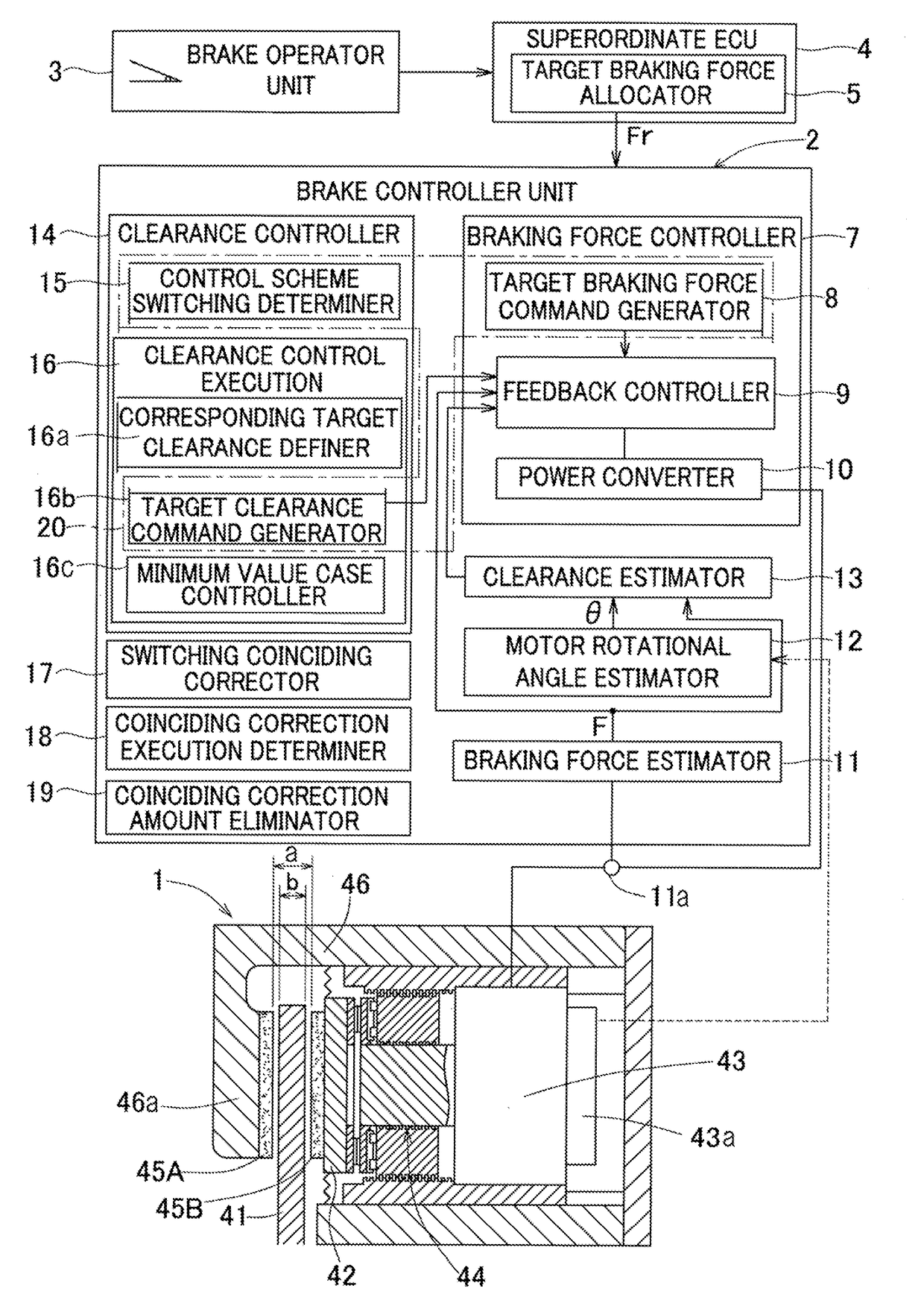
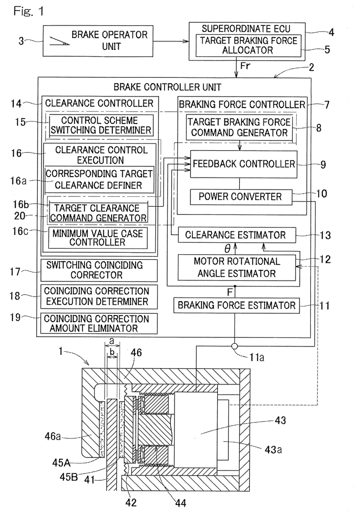
[0046]Embodiments of the present invention will now be described with reference to FIGS. 1 to 5. The illustrated electric brake device is intended to be employed for braking a wheel of a vehicle such as an automotive vehicle and may be formed by a brake main unit 1 which is a mechanical unit and a brake controller unit 2 which controls the brake main unit 1.

[0047]The brake main unit 1 may include a brake rotor 41 configured to rotate with the wheel, a frictional material mount 42, an electric motor 43, and a motion converter mechanism 44 configured to convert a rotary driving force of the motor 43 into a motion of the frictional material mount 42 in a direction towards or away from the brake rotor 41. The brake main unit 1 may be of a disc brake type in which the disc-shaped brake rotor 41 is intended to be clamped between a frictional material 45A mounted to a pawl portion 46a at a free end of a brake caliper 46 and a frictional material 45B mounted to the frictional material mount...


PUM


Abstract

Improved maneuverability, improved followability towards a target braking force and enhanced brake feeling when a low braking force is being effected may be achieved. A brake controller unit may include a clearance estimator which may be configured to use a rotational angle θ of a motor to estimate a clearance, inclusive of negative values, between a frictional material and a brake. A target braking force Fr may be compared with a switch-determining braking force Frsw, so that clearance control based on a target clearance Cr may be performed when the frictional material is in approximate-contact state corresponding to the target braking force Fr being low, and so that braking force control may be performed when it is equal to or greater than the switch-determining braking force Frsw.

Description

CROSS REFERENCE TO THE RELATED APPLICATION[0001]This application is a continuation application, under 35 U.S.C. §111(a), of international application No. PCT / JP2015 / 078294, filed Oct. 6, 2015, which is based on and claims Convention priority to Japanese patent application No. 2014-211500, filed Oct. 16, 2014, the entire disclosure of which is herein incorporated by reference as a part of this application.BACKGROUND OF THE INVENTION[0002]Field of the Invention[0003]The present invention relates to an electric brake device that may be applied to a vehicle such as various types of automotive vehicles and relates, in particular, to control thereof[0004]Description of Related Art[0005]In the technical field of conventional electric brake devices, an electric linear actuator using planetary rollers has been proposed (Patent Document 1). An electric brake using a linear motion mechanism, an electric motor and a speed reducer or reduction gear has also been proposed (Patent Document 2). Fur...

Claims


Application Information

Patent Timeline
03 Aug 2017
Publication
US20170217409A1
IPC
B60T8/172; B60T13/74; B60T8/17; F16D65/18; B60T7/12
CPC
B60T8/172; F16D65/18; B60T7/12; F16D2121/24; B60T13/741; F16D2125/34; B60T8/17; F16D2125/40
Inventors
MASUDA, YUI