Electronic part and method of producing the same
a technology of electronic parts and production methods, applied in the field of electronic parts, can solve problems such as increased production costs, and achieve the effect of reducing the area of electronic parts
- Summary
- Abstract
- Description
- Claims
- Application Information
AI Technical Summary
Benefits of technology
Problems solved by technology
Method used
Image
Examples
first embodiment
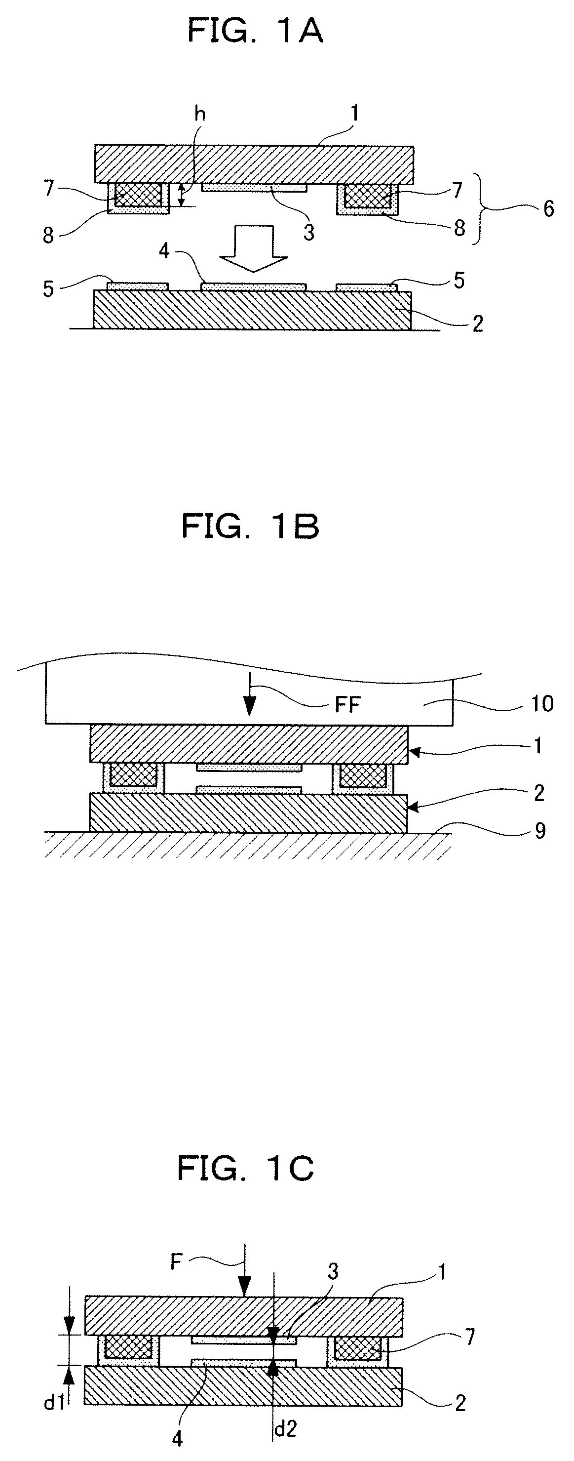
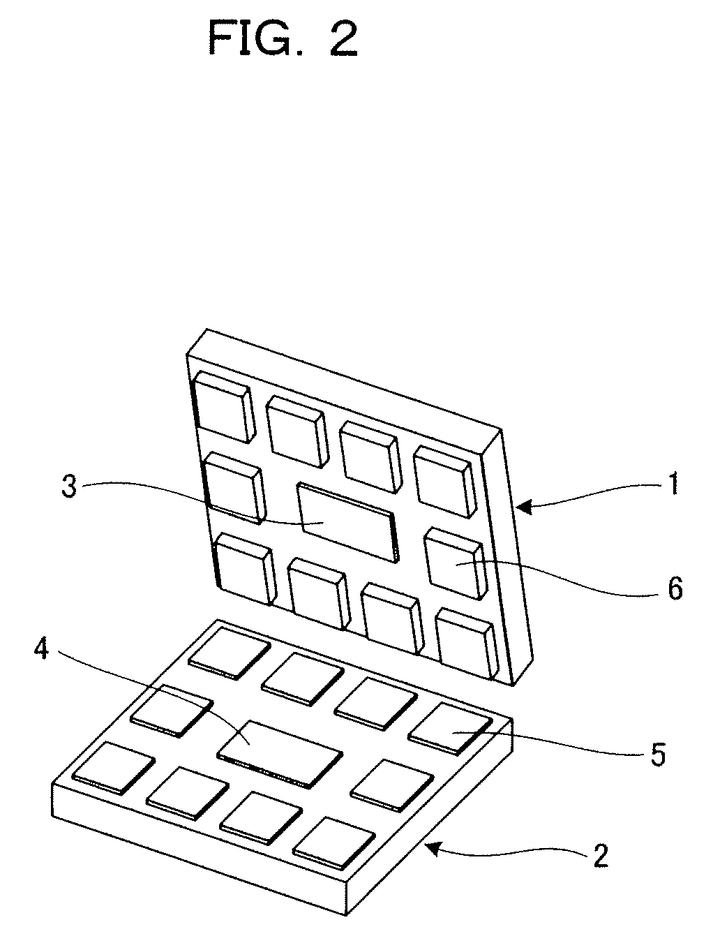
[0043]FIGS. 1A to 1C and FIG. 2 show a first embodiment of the present invention.
[0044]An electronic part shown in FIG. 1C has a device substrate 1, on which a functional portion is formed, and a bonding substrate 2 bonded together so as to cover each other with a gap d1 therebetween. Furthermore, the functional portion refers to a portion that functions so that the gap d1 changes as a result of applying a force or voltage and the like. More specifically, this electronic part is an electrostatic capacitance detecting type of sensor, and the functional portion is composed such that the central portion of the device substrate 1 is elastically deformed by the action of a force F, and a gap d2 changes between a first detecting electrode 3 provided on the device substrate 1 and a second detecting electrode 4 provided on the bonding substrate 2.
[0045]As shown in FIG. 1A and FIG. 2, a first electrode portion 5 is formed on the bonding substrate 2. A second electrode portion 6 is formed on ...
second embodiment
[0053]FIGS. 3A, 3B and 3C show a second embodiment of the present invention.
[0054]Although Au was used for both the first electrode portion 5 and the bump pattern 8 and both were subjected to direct bonding in the first embodiment, this second embodiment differs from the first embodiment only in that a molten metal 11 such as solder is formed as a bump pattern 8 on the Ni of a core pattern 7 as shown in FIG. 3A.
[0055]When a device substrate 1 and a bonding substrate 2 formed in this manner are clamped between clamping jigs 12a and 12b provided with a heating apparatus as shown in FIG. 3B, and then heated to a temperature equal to or higher than the melting point of the molten metal 11 together with clamping with a load FF, together with the Au of a first electrode portion 5 undergoing plastic deformation, the molten metal 11 becomes a liquid, thereby making it possible to absorb variations in pattern height during bonding and realize stable, high-quality bonding. When cooled while i...
third embodiment
[0057]FIGS. 4A, 4B and 4C show a third embodiment of the present invention.
[0058]Although Au was used for both the first electrode portion 5 and the bump pattern 8 and both were bonded by direct bonding in the first embodiment, this third embodiment differs only in that an electrically conductive adhesive 13, such as a paste in which a fine metal powder such as Ag, Cu or Au is dispersed in an adhesive, is formed as a bump pattern 8 on the Ni of a core pattern 7 as shown in FIG. 4A.
[0059]When a device substrate 1 and a bonding substrate 2 formed in this manner are clamped between clamping jigs 12a and 12b provided with a heating apparatus as shown in FIG. 4B, and then heated to a temperature equal to or higher than the curing temperature of the electrically conductive adhesive 13 together with clamping with load FF, together with the Au of a first electrode portion 5 undergoing plastic deformation, the electrically conductive adhesive 13 is heat-cured, the device substrate 1 and bond...
PUM
 Abstract
Description
Claims
Application Information
 - R&D
- Intellectual Property
- Life Sciences
- Materials
- Tech Scout
- Unparalleled Data Quality
- Higher Quality Content
- 60% Fewer Hallucinations
Browse by: Latest US Patents, China's latest patents, Technical Efficacy Thesaurus, Application Domain, Technology Topic, Popular Technical Reports.
© 2025 PatSnap. All rights reserved.Legal|Privacy policy|Modern Slavery Act Transparency Statement|Sitemap|About US| Contact US: help@patsnap.com


