Electric brake apparatus for vehicle

a technology of electric brakes and brake pads, which is applied in mechanical devices, brake systems, transportation and packaging, etc., can solve the problems of complex and troublesome drive control, and achieve the effects of accurate detection, simplified structure and arrangement, and good brake feeling

Active Publication Date: 2015-12-08
TOYOTA JIDOSHA KK
View PDF22 Cites 4 Cited by
  • Summary
  • Abstract
  • Description
  • Claims
  • Application Information

AI Technical Summary

Benefits of technology

[0006]However, in the conventional electric brake control apparatus and method and the conventional electric brake apparatus, in order to secure a proper clearance between the brake rotation body and the brake friction body, it is necessary to finely drive the electric motor or the electrical actuating means by controlling, for example, an inverter circuit or the like as in the case of driving the electric motor or the electrical actuating means at the time of braking. Therefore, the drive control becomes complex and troublesome. Also, since electric power must be supplied to the electric motor or the electrical actuating means so as to secure the clearance, there remains room for improvement from the viewpoint of energy saving.
[0023]By virtue of these configurations, there can be provided load detection means for detecting the load corresponding to the distortion generated due to the pressing force applied from the electric drive means to the piston. In this case, specifically, the load detection means can be provided on the pressing force transmission means which constitutes the electric drive means. Therefore, the load detection means can detect the load corresponding to the distortion generated in the pressing force transmission means as a result of transmission of the pressing force. Also, the load detection means can be formed of a pressure sensitive rubber whose resistance changes in accordance with the distortion generated due to deformation thereof, and the load corresponding to the resistance which changes in accordance with the deformation caused by the transmitted pressing force can be detected. By virtue of these, the load (i.e., the pressing force) can be accurately detected by a considerably simplified structure and arrangement. Therefore, for example, when a pressing force is applied to the piston by driving the electric motor of the electric drive means, a proper pressing force corresponding to a brake operation by a driver can be applied, whereby the driver can sense a good brake feeling.

Problems solved by technology

Therefore, the drive control becomes complex and troublesome.

Method used


Image

  • Electric brake apparatus for vehicle
  • Electric brake apparatus for vehicle
  • Electric brake apparatus for vehicle

Examples


first embodiment

[0043]a. First Embodiment

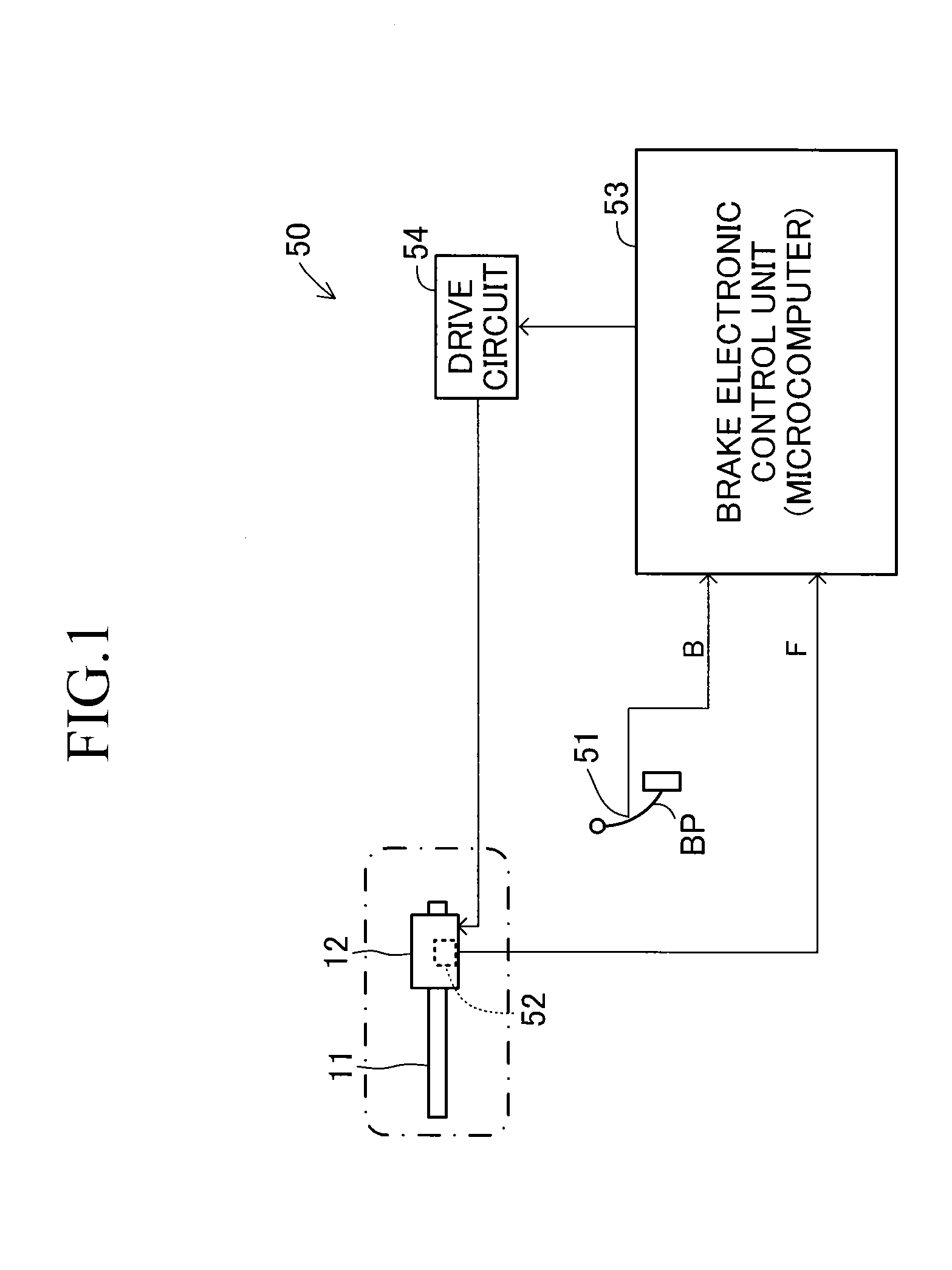
[0044]An embodiment of the present invention will now be described in detail with reference to the drawings. FIG. 1 schematically shows an electric brake apparatus according to a first embodiment of the present invention.

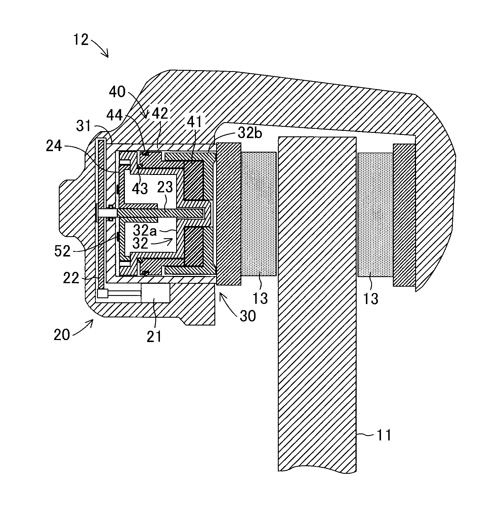
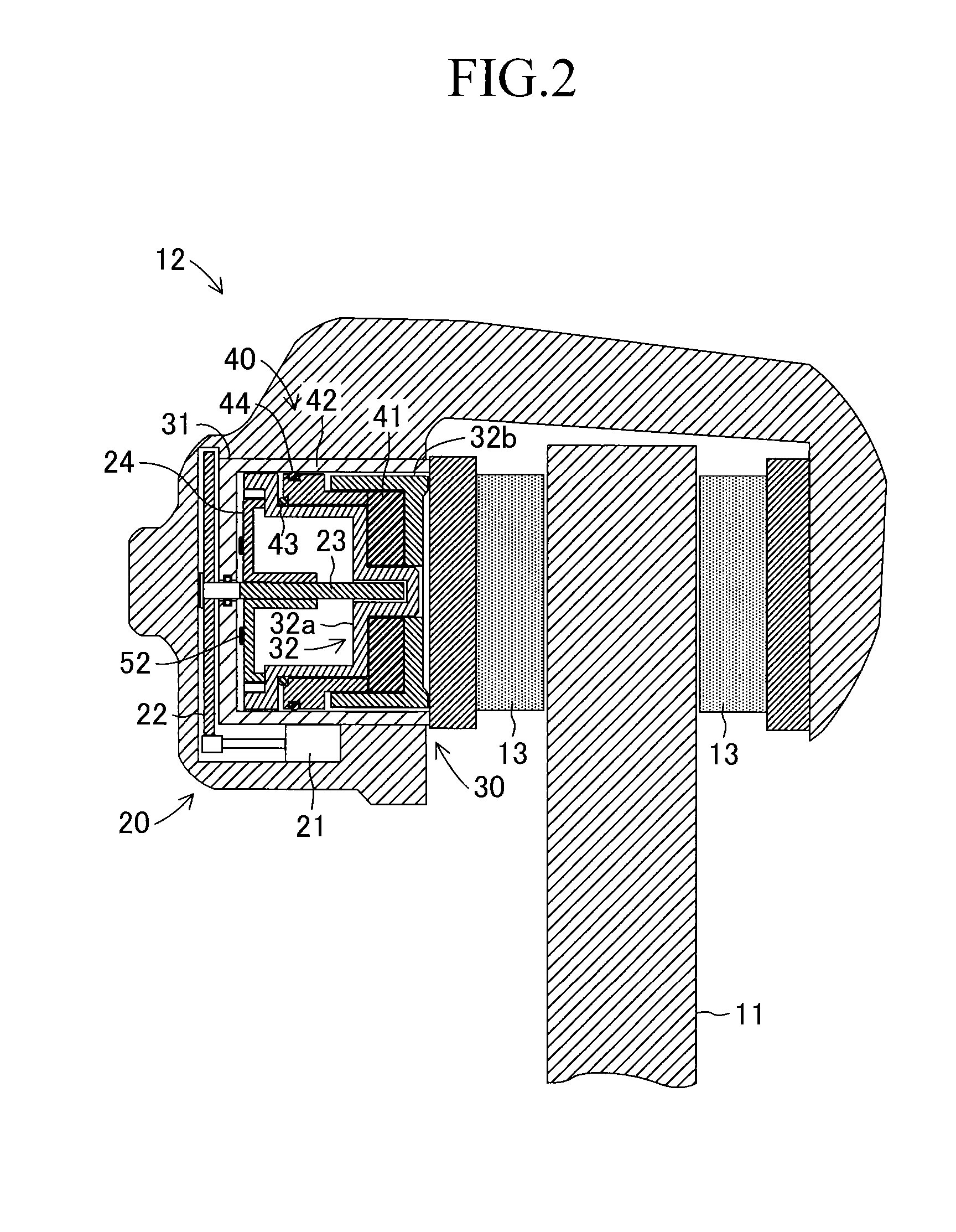
[0045]This electric brake apparatus includes a disc rotor 11 (a brake rotation body) which rotates unitarily with a wheel about the rotation axis of an axle, and an electric caliper 12 supported by an unillustrated mounting bracket fixed to a vehicle body such that the electric caliper 12 is movable along the direction of the rotation axis of the disc rotor 11. Notably, although FIG. 1 schematically shows only one wheel of a vehicle, the electric brake apparatus may be provided for each of left and right front wheels of the vehicle, each of left and right rear wheels of the vehicle, or each of all the wheels of the vehicle.

[0046]The electric caliper 12 is electrically controlled in response to a driver's brake operation so as to bring fricti...

second embodiment

[0094]b. Second Embodiment

[0095]In the above-described first embodiment, when the brake pedal BP is operated by a driver, the brake ECU 53 drives and controls the brake motor 21 so as to apply a braking force to a rotating wheel. However, the electric brake apparatus of the present invention may be embodied such that when a braking force is to be applied to a rotating wheel, like a known brake apparatus, the piston is advanced through use of oil pressure (hydraulic pressure) of brake fluid so as to bring the friction pad into pressure contact with the frictional sliding surface of the disc rotor, and the electric brake apparatus operates as a so-called electric parking brake apparatus for braking rotation of a wheel when the vehicle is parked or stopped. This second embodiment will now be described. Portions identical to those of the first embodiment are denoted by the same reference numerals, and their descriptions will not be repeated.

[0096]In this second embodiment, a brake fluid...


PUM


Abstract

An electric caliper includes an electric drive mechanism which generates a pressing force for pressing a friction pad against a disc rotor, and a retraction mechanism provided in a piston of a pressing mechanism. The mechanism includes a reversing member which is compressed by a force transmission portion and a pressing portion of the piston to thereby generate a reverse force. Also, the mechanism includes a movable element which relatively retracts due to the reverse force, and a first elastic member which is compressed by the movable element and the advancing force transmission portion to thereby apply a restoring force. Thus, in the mechanism, the reversing member generates the reverse force as a result of advancement of the force transmission portion, and the movable element relatively retracts due to the reverse force and compresses the first elastic member. When free rotation (no-load rotation) of a brake motor of the mechanism is permitted, the restoring force generated as a result of compression of the first elastic member is applied to the force transmission portion, whereby the piston is retracted.

Description

TECHNICAL FIELD[0001]The present invention relates to an electric brake apparatus for a vehicle which includes a brake rotation body which rotates unitarily with a wheel, and an electric caliper which presses a brake friction member against the brake rotation body through use of electrical power.BACKGROUND ART[0002]Conventionally, there have been known an electric brake control apparatus and an electric brake control method as disclosed in, for example, Japanese Patent Application Laid-Open (kokai) No. 2008-57642. In the conventional electric brake control apparatus and electric brake control method, when a brake friction body satisfies a condition set in advance, the amount of electricity supplied to an electric motor is controlled such that the electricity supply amount gradually decreases between a preset first electricity supply amount and a second electricity supply amount smaller than the first electricity supply, and a standby position of the brake friction body is set on the...

Claims


Application Information

Patent Timeline
Patent Type & Authority Patents(United States)
IPC IPC(8): F16D55/08B60T13/74B60T13/58F16D65/18F16D121/06F16D121/24F16D123/00F16D125/40F16D127/02
CPCB60T13/745B60T13/588B60T13/741F16D65/18F16D2121/06F16D2121/24F16D2123/00F16D2125/40F16D2127/02
Inventor ISONO, HIROSHI
Owner TOYOTA JIDOSHA KK
Why Eureka
Try Eureka