Pneumatically-operated rigid linear chain and sprocket actuator for deploying a vehicle snow chain traction system

a linear chain and pneumatic operation technology, applied in the direction of wheels, vehicle components, non-skid devices, etc., can solve the problems of system being too bulky for certain applications, arc of rotation of the support member 108, and limited to less than about 150 degrees, so as to minimize friction between the idler bar and the rack, the effect of rapid retraction and rapid deploymen

Inactive Publication Date: 2017-08-15
MCKENNA SHANE EVAN +1
View PDF12 Cites 3 Cited by
  • Summary
  • Abstract
  • Description
  • Claims
  • Application Information

AI Technical Summary

Benefits of technology

[0024]The present invention answers the needs expressed in the foregoing section. A new system is provided for rapid deployment and rapid retraction of vehicle ice and snow chain traction systems. The new system includes a pneumatic cylinder having a cylindrical chamber enclosing a piston that is pneumatically-movable bidirectionally. A control rod coupled at one end to the piston passes through an end of the chamber and is coupled to a rack that is linearly movable within a sealed, grease-containing case. The rack is formed from a series of equally-spaced roller pins which are secured between parallel walls of a rack frame. The roller pins of the rack engage a sprocket that is affixed to a rotatable shaft, which is rigidly coupled an actuator arm of the rapidly-deployable vehicle ice and snow chain traction system. The rotatable shaft turns in sealed ball bearing races mounted in bearing retainers that are bolted to the case. As the rack is moved back and forth, the actuator arm swings through an arc that—depending on the displacement of the control rod and the length of the rack, can be greater than 180 degrees. For a preferred embodiment of the invention, the piston is moved bidirectionally with compressed air. Position of the rack at limits of travel is maintained by air pressure applied to one side of the piston. Proper clearance between the sprocket and the rack is provided by tightening or loosening an play-adjustment bolt that secures one end of a rocking idler bar that is equipped with an end roller at the opposite end that minimizes friction between the idler bar and the rack.

Problems solved by technology

A major problem associated with chain traction systems deployed by pneumatic cylinders is that the arc of rotation of the support member 108, on which the spindle 107 and friction disc 105 are mounted, is limited to less than about 150 degrees.
In addition, the system may be too bulky for certain applications, such as installation on light-duty pickup trucks.
One major problem associated with prior art gear-driven deployment systems, on the other hand, is that uneven road surfaces imposed a potentially destructive shock load on the gear train when the chain traction system was in a retracted state.
The shock loads had a tendency to shear the teeth off of gears in the deployment gear train.
The shock loads could also fracture the housing used to contain the gear train.
Another major problem associated with gear-driven deployment systems is that of grit, water, and corrosion related to inadequate protection of the gear train.
Without proper sealing, the life expectancy of such systems would likely be no more than one winter season.
This innovative deployment system, which was initially marketed by the assignee of the present invention, experienced multiple problems, including circuit design problems, water leakage into the circuit components, and a propensity to deploy automatically, which was caused by vibration and shocks experienced by the vehicle on which it was mounted.
Though some of the problems were eventually solved, the unit soon gained notoriety as a lemon in the industry, which doomed its acceptance in the marketplace.

Method used


Image

  • Pneumatically-operated rigid linear chain and sprocket actuator for deploying a vehicle snow chain traction system
  • Pneumatically-operated rigid linear chain and sprocket actuator for deploying a vehicle snow chain traction system
  • Pneumatically-operated rigid linear chain and sprocket actuator for deploying a vehicle snow chain traction system

Examples


Embodiment Construction

[0037]The pneumatically-operated rigid linear chain and sprocket actuator for rapidly deploying and retracting a vehicle snow chain traction system will now be described in detail with reference to the attached drawing figures.

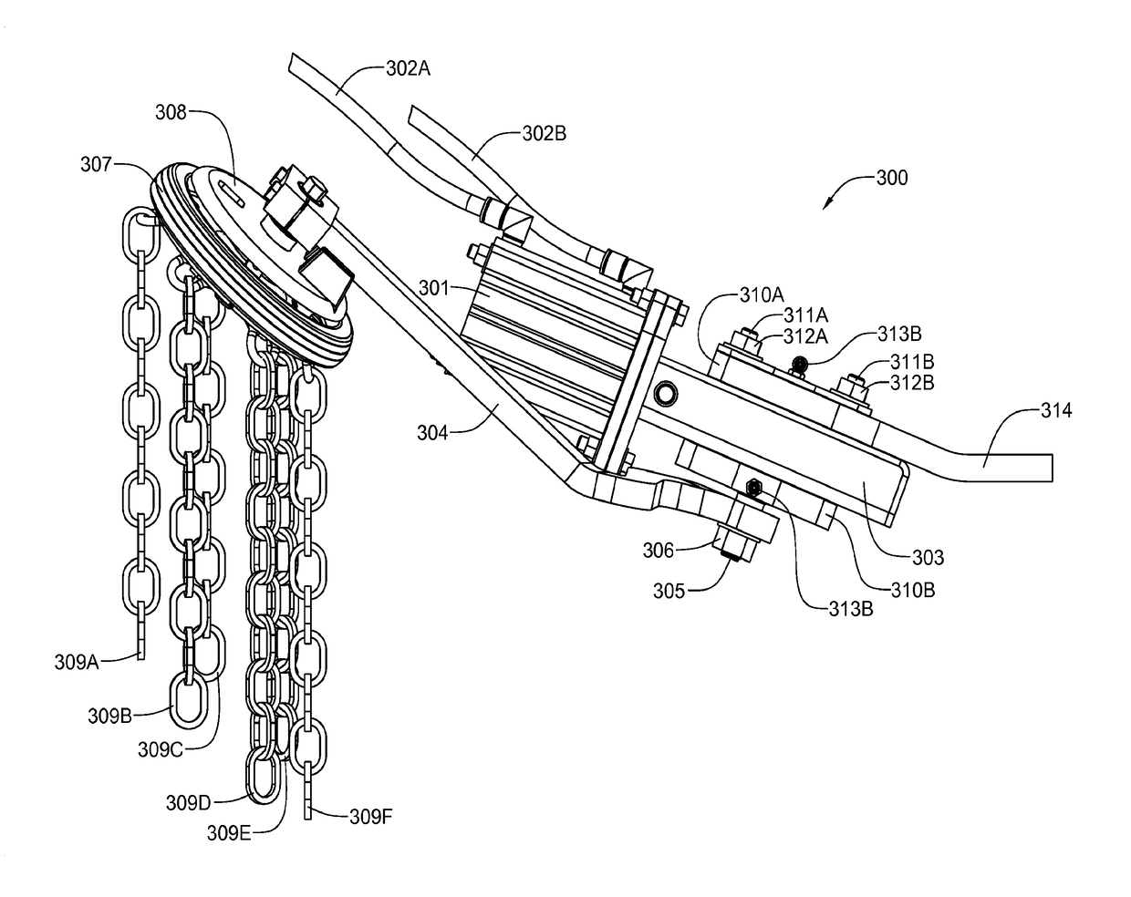
[0038]Referring now to FIG. 3, the new vehicle snow chain traction system 300 includes a pneumatic cylinder assembly 301 having a cylindrical chamber enclosing a piston (internal components of the pneumatic cylinder assembly are not shown in this view) that is pneumatically-movable bidirectionally by means of compressed air delivered by compressed air lines 302A and 302B. The pneumatic cylinder assembly 301 is bolted to a rigid linear chain and sprocket actuator unit 303. An actuator shaft 304, on which the internal sprocket (now shown in this view) is secured, protrudes through one side of the actuator unit 303. A deployment arm 304 is rigidly secured to the protruding end of the actuator shaft 305 with a lock nut 306. For a preferred embodiment of the invent...


PUM


Abstract

A unit for rapid deployment and retraction of chain traction systems for vehicles includes a pneumatic cylinder having a cylindrical chamber enclosing a piston that is pneumatically-movable bidirectionally. A control rod coupled at one end to the piston passes through an end of the chamber and is coupled to a rack linearly movable within a sealed, grease-containing case. The rack is formed from a series of equally-spaced roller pins secured between parallel walls of a rack frame. The roller pins of the rack engage a sprocket affixed to a rotatable shaft to which is rigidly coupled an actuator arm of the rapidly-deployable vehicle ice and snow chain traction system. As the rack is moved back and forth, the actuator arm swings through an arc that—depending on the displacement of the control rod and the length of the rack, can be greater than 180 degrees.

Description

BACKGROUND OF THE INVENTION[0001]Field of the Invention[0002]This invention relates, generally, to vehicle ice and chain traction systems which may be both rapidly deployed and rapidly retracted. More particularly, it relates to an actuator apparatus in which a pneumatic cylinder linearly motivates a slidable rack comprised of equally-spaced, parallel roller pins mounted thereon. The roller pins engage a rotatable sprocket that is coupled to a chain traction system deployment arm.[0003]Description of Related Art[0004]Rapidly-deployable chain traction systems, which may be characterized generally as systems which fling short chain or cable segments beneath a road tire, have been known for some 90 years. Such a system is disclosed in U.S. Pat. No. 1,045,609 and in German Pat. No. 266,487 to W. H. Putnam for an ANTISKIDDING DEVICE. Throughout the years, various modifications and improvements have been made by numerous inventors. The following list is a representative list of a dozen ot...

Claims


Application Information

Patent Timeline
Patent Type & Authority Patents(United States)
IPC IPC(8): B60C27/14B60B39/00
CPCB60B39/006B60C27/14B60B2900/551B60B2900/721
Inventor MCKENNA, SHANE EVANATKINSON, JR., JOHN HORACE
Owner MCKENNA SHANE EVAN
Why Eureka
Try Eureka