Deep hole machining device and method

A processing device and deep hole technology, used in metal processing equipment, manufacturing tools, boring/drilling and other directions, can solve the problems of troublesome process, complex process, high equipment requirements, reduce the cumulative error of transmission, reduce the complexity, The effect of improving machining accuracy

Pending Publication Date: 2019-02-15
YICHANG JIANGXIA MARINE MACHINERY
View PDF1 Cites 3 Cited by
  • Summary
  • Abstract
  • Description
  • Claims
  • Application Information

AI Technical Summary

Problems solved by technology

[0002] The existing processing of high-precision deep-hole parts mainly relies on the programming of CNC deep-hole drilling machines. The disadvantage is that the requirements for equipment are high, and the investment cost is high. Before processing, pilot holes need to be drilled, and the process is troublesome.
Moreover, for some parts that require high precision and large size, the existing CNC deep hole drilling machine still cannot meet the requirements in terms of accuracy.
[0003] Chinese patent document CN107350500A describes a method for processing

Method used


Image

  • Deep hole machining device and method
  • Deep hole machining device and method
  • Deep hole machining device and method

Examples


Embodiment 1

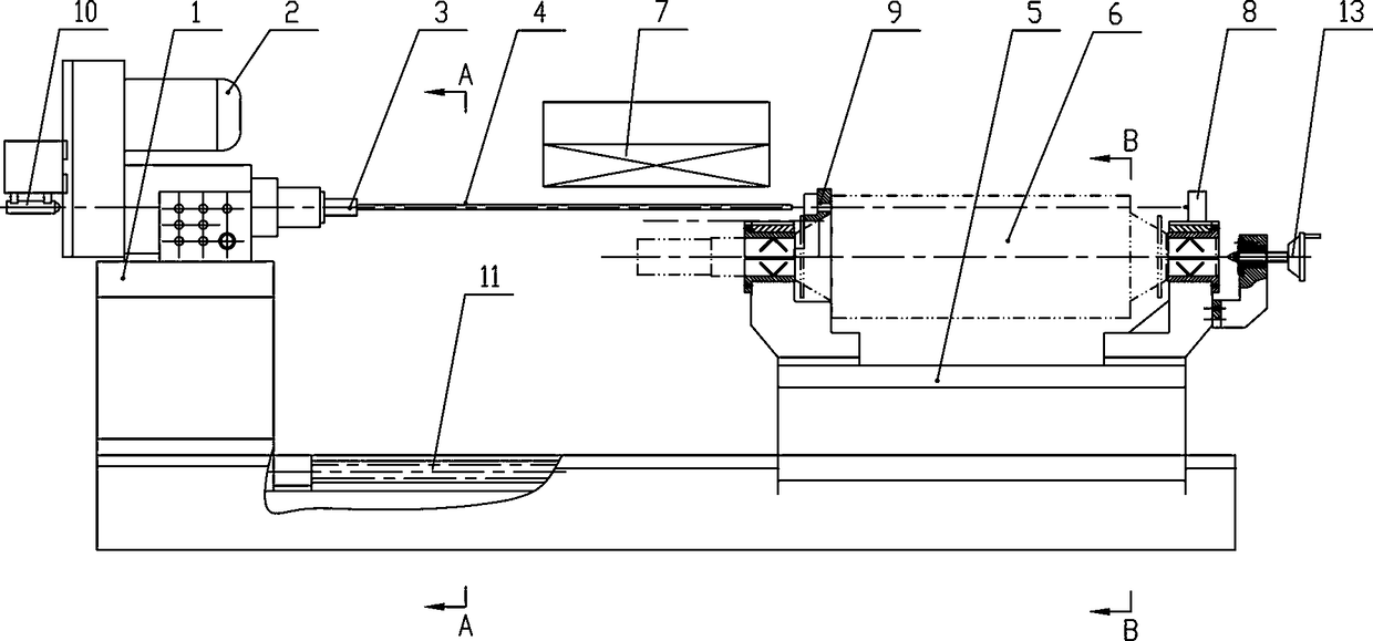
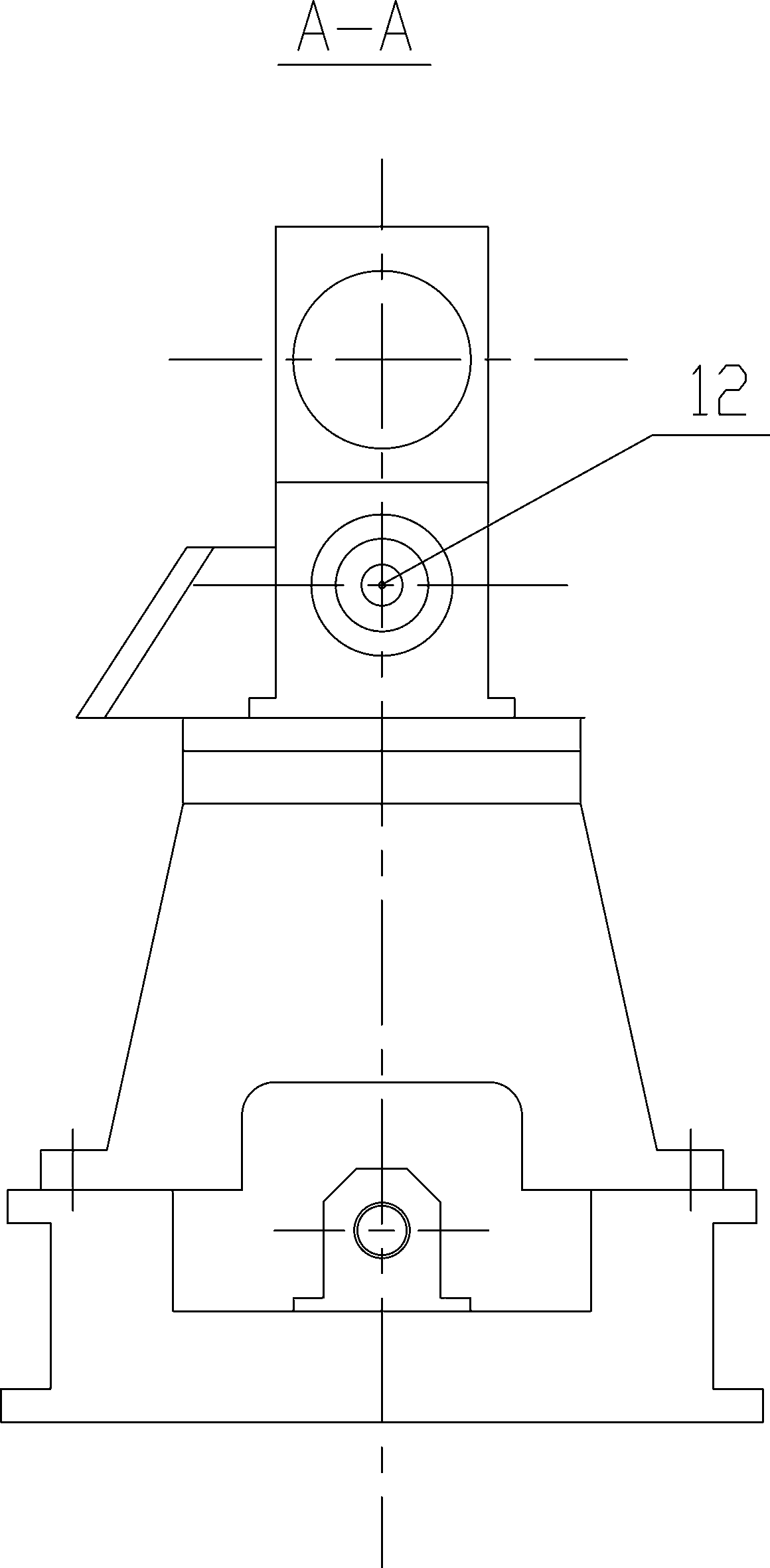
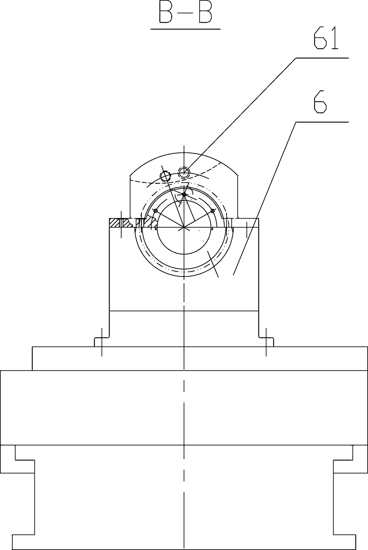
[0031] Such as Figure 1~3 Among them, a deep hole processing device includes a bed 1, a drilling power head 2 is fixed on the bed 1, and a deep hole drill 4 is installed on the drilling power head 2. In the drilling power head 2, The drill base is connected with the motor through the transmission mechanism. The deep hole drill bit 4 is fixedly installed on the drill base. The workbench 5 is slidably installed on the bed 1 through the guide rail. They are also connected by a lead screw nut mechanism 11, the workpiece 6 is clamped on the workbench 5, and the feed of the workpiece is realized by the lead screw nut mechanism 11. By adopting the feeding method of the worktable 5, the transmission mechanism is reduced in the drilling power head 2, that is, the cumulative error caused by the transmission mechanism is reduced.

[0032] In a preferred solution, the workpiece 6 is rotatably clamped on the fixture 9 of the workbench 5 through a shaft, and the fixture 9 is also provided...

Embodiment 2

[0039] On the basis of Example 1, the preferred scheme is as figure 1 , 5 Among them, a laser-assisted calibration device is also provided. The structure is: a laser emitting device 10 is provided at one end of the bed, and a photoelectric collector 8 is provided at the other end. The laser emitting device 10 is used to emit a beam of collimated laser light through the deep hole. The drill bit 4 and the workpiece 6 are received by the photoelectric collector 8 .

[0040] In a preferred solution, the laser emitting device 10 is fixed on the drilling power head 2, and the laser emitting device 10 is used to emit a beam of laser beams along the axis of the deep hole drill 4, between the drilling power head 2 and the deep hole drill 4 There is a correction hole 12 on it;

[0041] The photoelectric collector 8 is fixed on the side of the fixture 9 away from the deep hole drill 4 , and an array of photosensitive elements is arranged on the photoelectric collector 8 . Preferably, ...


PUM


Abstract

The invention provides a deep hole machining device and method. The deep hole machining device comprises a machine tool body, the machine tool body is fixedly provided with a drilling power head, a deep hole drilling head is installed on the drilling power head, a workbench is slidably installed on the machine tool body through a guide rail, the workbench and the machine tool body are further connected through a screw rod nut mechanism, a workpiece is clamped on the workbench, the deep hole machining device is further provided with a laser assisted calibration device and an electromagnetic deviation correcting device, a deviation correcting hole is punched in the position of the workpiece to be machined by laser, a laser beam emitted by a laser emitting device is made to fall on a photoelectric collector, and deviation of the deep hole drilling head is corrected in real time through the electromagnetic deviation correcting device. By means of adoption of the above scheme of the deep hole machining device and method, the structure is simplified, and improvement of the machining precision is facilitated; by means of the arrangement of the laser assisted calibration device, online precision calibration can be realized, and deviation errors can be detected in real time according to the collimating laser shape change and different positions of the photoelectric collector where the laser falls on; and by means of the arrangement of the electromagnetic deviation correcting device, the deviation of the deep hole drilling head can be corrected in real time, and the machining precision is further improved.

Description

technical field [0001] The invention relates to the field of high-precision deep hole processing, in particular to a deep hole processing device and method. Background technique [0002] The existing processing of high-precision deep-hole parts mainly relies on the programming of CNC deep-hole drilling machines. The disadvantage is that the requirements for equipment are high, and the investment cost is relatively high. Before processing, pilot holes need to be drilled, and the process is cumbersome. Moreover, for some parts that require high precision and large size, the existing CNC deep hole drilling machines still cannot meet the requirements in terms of precision. [0003] Chinese patent document CN107350500A records a method for processing deep holes, which adopts segmental processing and corrects the datum for processing, and assists in fine boring and honing processes, which can process deep holes, but this scheme is mainly aimed at deep holes with larger diameters. ...

Claims


Application Information

Patent Timeline
IPC IPC(8): B23B41/02
CPCB23B41/02
Inventor 徐艳梅苏强
Owner YICHANG JIANGXIA MARINE MACHINERY
Why Eureka
Try Eureka