Offset correction program and electronic compass

US20090012733A1Inactive Publication Date: 2009-01-08ALPS ALPINE CO LTD

Image

  • Offset correction program and electronic compass
  • Offset correction program and electronic compass
  • Offset correction program and electronic compass

Examples


Embodiment Construction

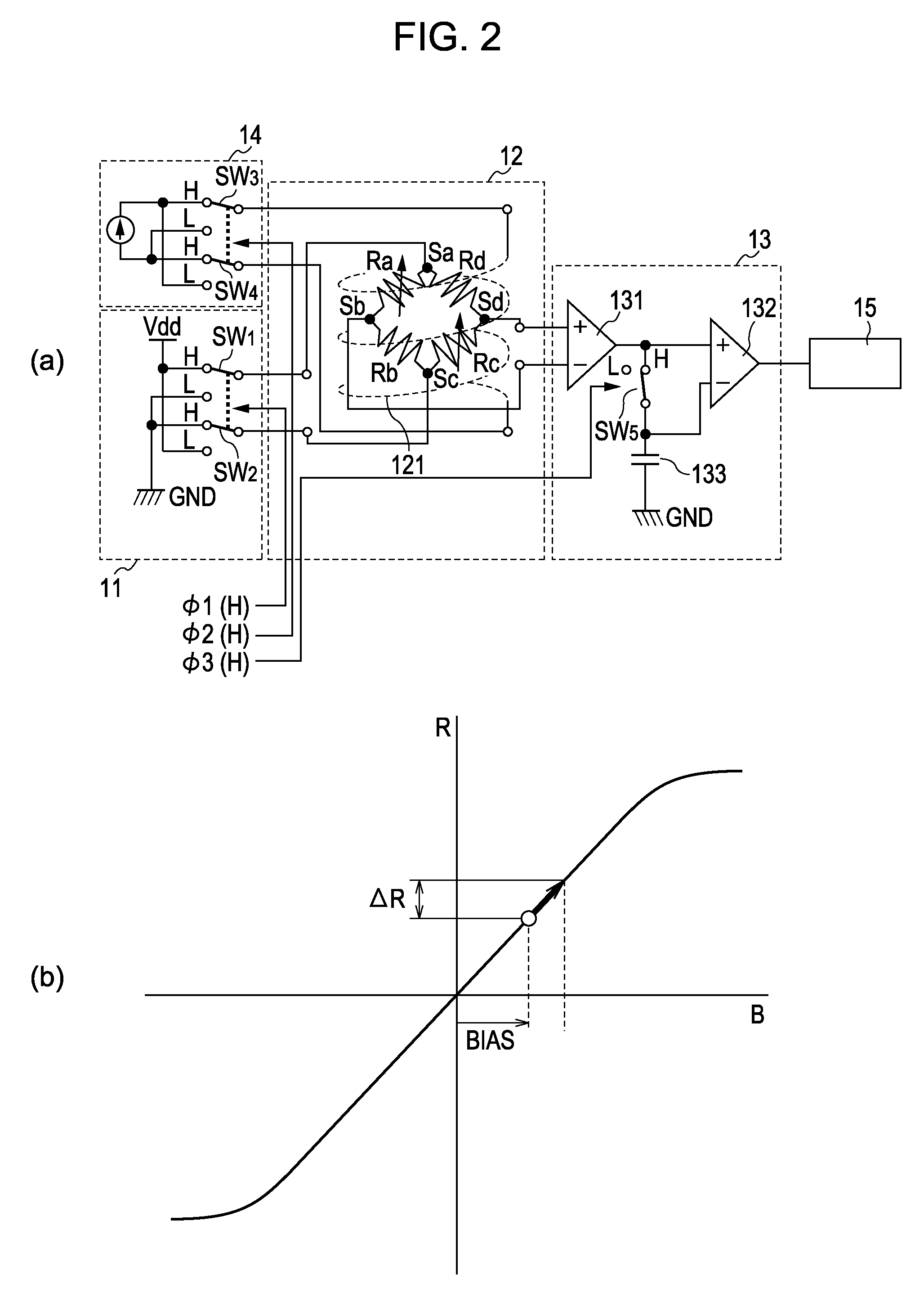
[0020]When a magnetoresistive element that shows changes in resistance that occur monotonically with a magnetic field is to be used, first, a bias magnetic field of one of the polarities is applied to invert the polarity of a voltage to be applied to the magnetoresistive element, thereby determining a voltage value corresponding to another magnetic field. Next, a bias magnetic field of the other polarity is applied to invert the polarity of a voltage to be applied to the magnetoresistive element, thereby determining a voltage value corresponding to another magnetic field. The two voltage values each contain an offset voltage. Therefore, by determining a difference between the voltage values corresponding to the other respective magnetic fields, which are determined in this manner, a voltage value corresponding to another magnetic field can be determined in a state in which the offset voltage is cancelled. As a result, magnetic detection in a state in which there is no offset voltage...


PUM


Abstract

When an external magnetic field is applied to a sensor unit 12 for various causes, a characteristics curve does not pass through an intersection point of resistance (voltage) and a magnetic field and is offset. That is, an offset voltage (Roff) occurs. In the present invention, in order to determine a correction value for canceling the offset voltage, a difference between output voltages is determined from two stages in which a bias magnetic field is inverted, and the bias magnetic field is controlled until the difference becomes approximately zero. Then, the corresponding bias magnetic field (the electrical current value) when the difference between the output voltages becomes approximately zero is set as a correction value (correction bias). As a result, since correction can be performed even if an offset voltage is applied, it is possible to accurately perform magnetic detection.

Description

CLAIM OF PRIORITY[0001]This is a continuation of International Application No. PCT / JP2007-053576, filed Feb. 27, 2007, which is incorporated herein by reference in its entirety.BACKGROUND OF THE INVENTION[0002]1. Field of the Invention[0003]The present invention relates to an offset correction program for correcting an offset to be applied to a magnetic sensor and an electronic compass including the offset correction program.[0004]2. Description of the Related Art[0005]When direction measurement is to be performed electronically, this is performed using a magnetic sensor for detecting an external magnetic field, such as the geomagnetism. A technology is known in which, when a direction is to be determined using a magnetic detection circuit including a magnetic sensor, an alternating-current magnetic field is applied to the magnetic sensor, and a voltage output from the magnetic sensor when the alternating-current magnetic field is applied is used.[0006]In this technology, magnetic s...

Claims


Application Information

Patent Timeline
08 Jan 2009
Publication
US20090012733A1
IPC
G01C17/38
CPC
G01C17/38; G01R33/091; G01R33/09; G01R33/0023
Inventors
YAMADA, YUKIMITSU; HIROBE, KISEI