Dust separating apparatus of a vacuum cleaner

a technology of dust separation apparatus and vacuum cleaner, which is applied in the direction of auxillary pretreatment, cleaning filter means, separation processes, etc., can solve the problems of increasing the resistance of the vacuum motor or even burning it out, affecting the performance and lifetime of the vacuum cleaner, and trouble for users, so as to increase the airflow volume withou, improve the performance, and increase the volume of the machine

Inactive Publication Date: 2011-02-08
KINGCLEAN ELECTRIC
View PDF17 Cites 25 Cited by
  • Summary
  • Abstract
  • Description
  • Claims
  • Application Information

AI Technical Summary

Benefits of technology

[0006]The object of the present invention is to provide a dust separating apparatus of a vacuum cleaner which comprises several removable second cyclone separators mounted around a first cyclone separator. The first and second cyclone separators respectively have a separate dust receiving cavity and separate dust collecting chambers, so that the dust could be thoroughly separated from the air to enable the expelled air cleaner without secondary pollution. Furthermore, the dust could be disposed independently for convenience.
[0025]2. The present invention comprises a first cyclone separator and several second cyclone separators, thereby increasing the airflow volume without the increase of the volume of the machine, and keeping a better performance.
[0026]3. The second cyclone separators of the present invention adopt an expanding configuration, i.e. the tapered barrel is of a small top end and a large bottom end. The cyclone inlet is located in the upper portion of the inlet barrel. The air flow decelerates in a centrifugal manner during revolving in the tapered barrel, thereby resulting in less pressure loss. Therefore, a better cleaning performance could be obtained.
[0027]4. The cyclonical chamber of the first cyclone separator of the present invention is isolated from a dust receiving cavity of the first cyclone separator by an inner cylinder body, thereby preventing dust at the bottom end of the barrel from being raised up under the cyclone, without causing secondary pollution.
[0028]5. The second cyclone separators of the present invention are set to be removable, and as an optional accessory of the vacuum cleaner. When the customers need vacuum cleaners of better performance, they simply need to add an accessory of the second cyclone separators to satisfy the requirement. The users can simply upgrade the vacuum cleaners of single cyclonical stage into two filtering stages by buying the accessory, which brings the users more convenience and increases their loyalty to the products.

Problems solved by technology

Otherwise, fine dust may clog the filtering apertures of the filtering devices, thereby increasing the resistance of the vacuum motor or even burning it out.
That will bring troubles to the users, and will affect the performance and lifetime of the vacuum cleaners.
However, with the reinforcement of the environment protection consciousness of the customers, vacuum cleaners of single stage can not meet their requirements.
However, the vacuum cleaners with two stages of separating apparatus may result in defects that the cyclone raises dust and cleaning the dust is inconvenient.
Therefore, different dust cups need developing for the design of the same contour of vacuum cleaners, thereby resulting in increased production cost and waste in design and production resources.

Method used


Image

  • Dust separating apparatus of a vacuum cleaner
  • Dust separating apparatus of a vacuum cleaner
  • Dust separating apparatus of a vacuum cleaner

Examples


first embodiment

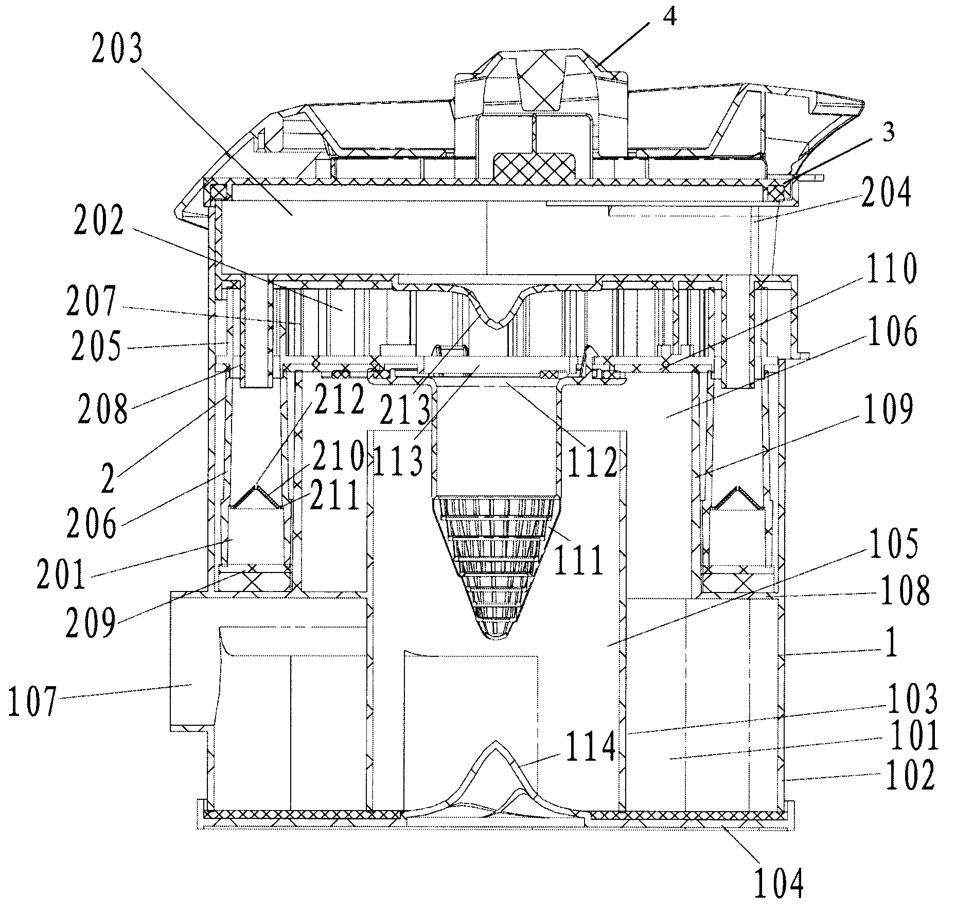
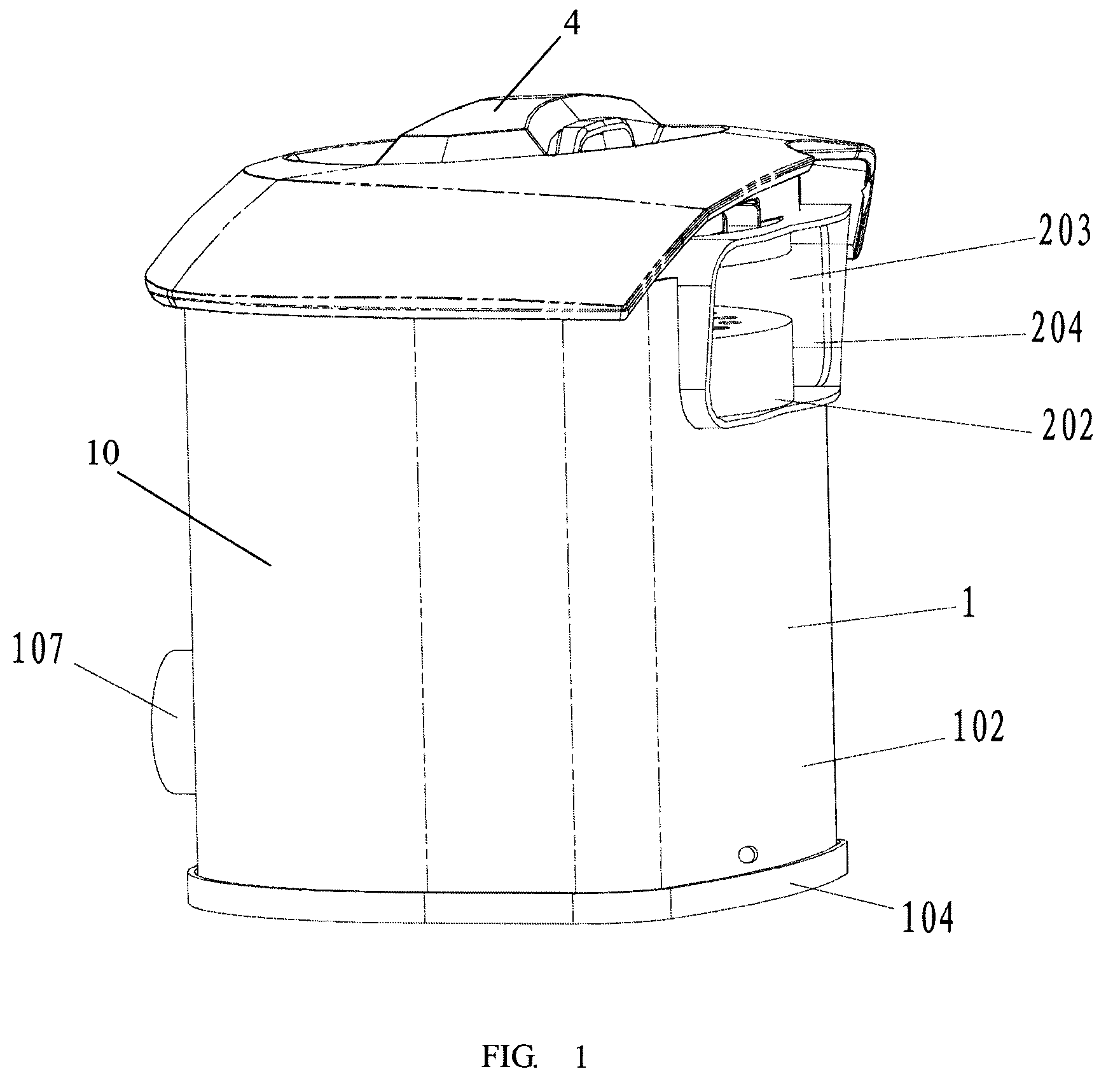
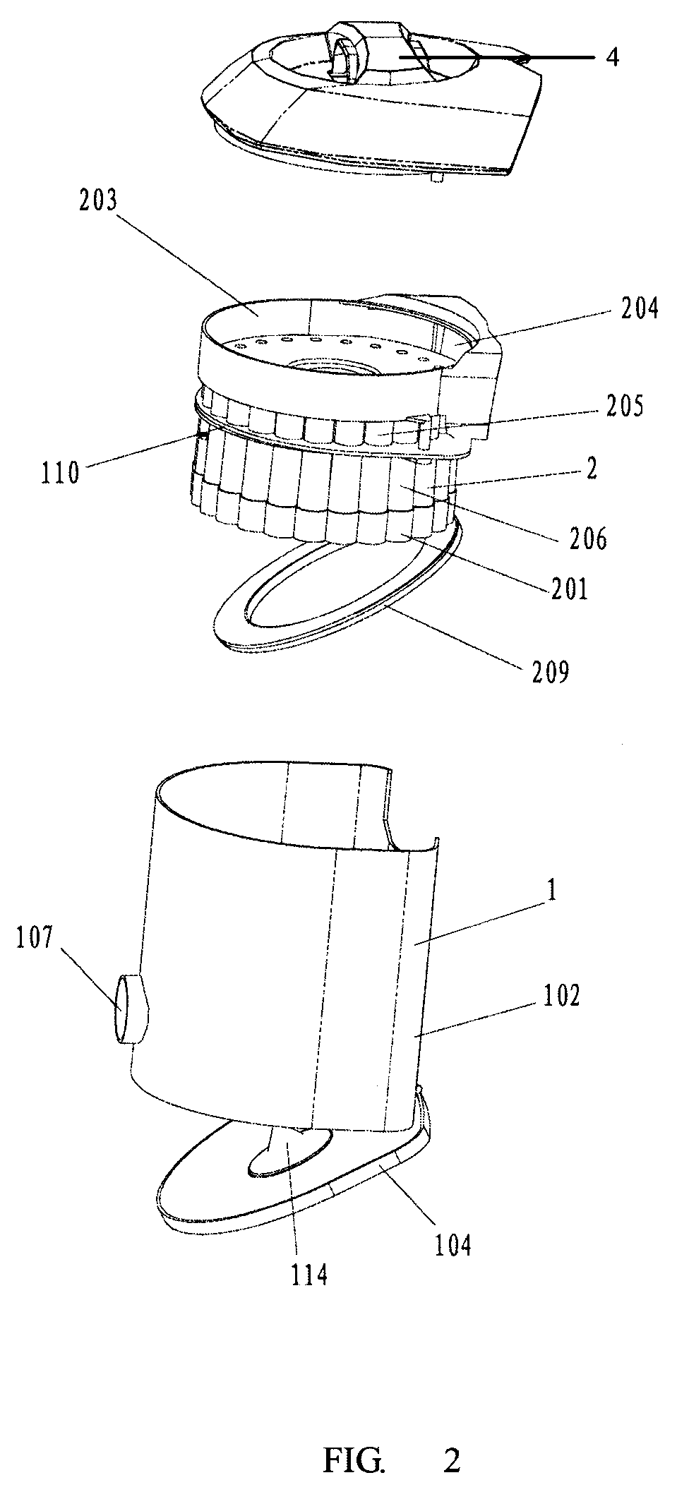
[0043]the present invention is shown in FIGS. 1-6. A dust separating apparatus of a vacuum cleaner is provided in this invention. It comprises a first cyclone separator 1 which is integrated and located within a housing 10, and several second cyclone separators 2 which are removably arranged around the first cyclone separator 1. The first cyclone separator 1 and the second cyclone separators 2 have respectively a separate dust receiving cavity 101 and separate dust collecting chambers 201.

[0044]As best seen in FIG. 4, the housing 10 includes an outer cylinder body 102 and an inner cylinder body 103 which share a common bottom cover 104, and therebetween a dust receiving cavity 101 is defined. A cyclonical chamber 105 is arranged in the inner cylinder body 103, and a cone-shaped protrusion 114 on the bottom cover 104 is arranged at the bottom of the inner cylinder body 103. A dust outlet 106 is arranged in the upper portion of the inner cylinder body 103, and an airflow inlet pipe 10...

third embodiment

[0056]FIG. 9 illustrates the dust separating apparatus in accordance with the invention, i.e. the second kind of fitting relationship between the first cyclone separator 1 and the second cyclone separator 2. In this embodiment, the air laden with dust enters the first cyclone separator 1 via the airflow inlet pipe 107, and is driven to rotate in clockwise direction by the generated cyclone. The air after the first filtering enters the tapered barrel 206 of the second cyclone separator for the second filtering under the guide of the guiding channel 5. Such arrangement can further guide the clean air to avoid secondary pollution. It should be understood, the “clockwise” mentioned here only points to the arrangement adopted in the embodiment as shown, and it is not restrictive.

[0057]Furthermore, the supporting member for supporting the second cyclone separator 2 in this invention is arranged to extend from the inner side of housing to its center. In the first embodiment of this inventi...


PUM

PropertyMeasurementUnit
resistanceaaaaaaaaaa
centrifugal forceaaaaaaaaaa
areaaaaaaaaaaa

Abstract

A dust separating apparatus of a vacuum cleaner, includes a housing, a first cyclone separator integrated within the housing, and second cyclone separators arranged around the first cyclone separator, wherein the second cyclone separators are removably mounted into the housing. The first and second cyclone separators respectively have a separate dust receiving cavity and separate dust collecting chambers.

Description

FIELD OF INVENTION[0001]The present invention relates to a dust separating apparatus of a vacuum cleaner.BACKGROUND OF THE INVENTION[0002]Usually a vacuum cleaner is provided with a cleaning device for filtering the dust-laden air sucked in with the dust and particles collected in a dust cup and discharging the filtered air. That is, the cleaning device of the traditional vacuum cleaner is actually a filtering device. Therefore, the users should have the filter devices cleaned or replaced after using for a while. Otherwise, fine dust may clog the filtering apertures of the filtering devices, thereby increasing the resistance of the vacuum motor or even burning it out. That will bring troubles to the users, and will affect the performance and lifetime of the vacuum cleaners.[0003]In recent years, according to the principle of cyclone separation, some vacuum cleaner manufacturers use a cyclone separator to replace the filtering device and achieve favorable results. Therefore, that has...

Claims


Application Information

Patent Timeline
Patent Type & Authority Patents(United States)
IPC IPC(8): B01D45/00
CPCA47L9/1625A47L9/1641A47L9/1683B01D45/12B04C5/13B04C5/185B04C5/24Y10S55/03
Inventor NI, ZUGEN
Owner KINGCLEAN ELECTRIC
Why Eureka
Try Eureka