Spindle motor

a spindle motor and spindle shaft technology, applied in the field of spindle motors, can solve the problems of reducing the coupling strength of the turntable with the rotating shaft, reducing increasing the overall size of the spindle motor, so as to prevent a rotational slip, improve the contact area of the rotating shaft, and prevent a data read error

Inactive Publication Date: 2013-12-10
HITACHI LG DATA STORAGE KOREA
View PDF12 Cites 0 Cited by
  • Summary
  • Abstract
  • Description
  • Claims
  • Application Information

AI Technical Summary

Benefits of technology

[0011]Accordingly, an object of the present invention is to provide a spindle motor, which improves a coupling strength of a turntable with a rotating shaft without an increase of volume or thickness.
[0023]As apparent from the above description, the spindle motor according to the present invention is advantageous in that a reinforcing part is provided on a turntable which is press-fitted over a rotating shaft, thus improving a contact area of the rotating shaft with the turntable, preventing a rotational slip between the rotating shaft and the turntable, and preventing the turntable from being placed obliquely relative to the rotating shaft, therefore preventing a data read error or a data write error while data is recorded in or read from an optical disk.

Problems solved by technology

As the turntable and the centering unit are coupled together to the rotating shaft of a limited length, a coupling area (or contact area) of the turntable with the rotating shaft is reduced, thus undesirably reducing a coupling strength of the turntable with the rotating shaft, and causing a rotational slip between the turntable and the rotating shaft.
Further, if thickness of the turntable increases so as to increase the coupling area of the rotating shall with the turntable, the overall size of the spindle motor undesirably increases.

Method used


Image

  • Spindle motor
  • Spindle motor
  • Spindle motor

Examples


Embodiment Construction

[0030]Hereinafter, exemplary embodiments of the present invention will be described in detail with reference to the accompanying drawings. For clarity and convenience of description, the size or shape of components shown in the drawings may not be illustrated to scale. Further, terminologies defined in consideration of the construction and effect of the present invention may be changed according to a user or operator intention or the custom. These terminologies should be interpreted as having meanings and concepts in keeping with the technical spirit of the present invention based on the overall detailed description.

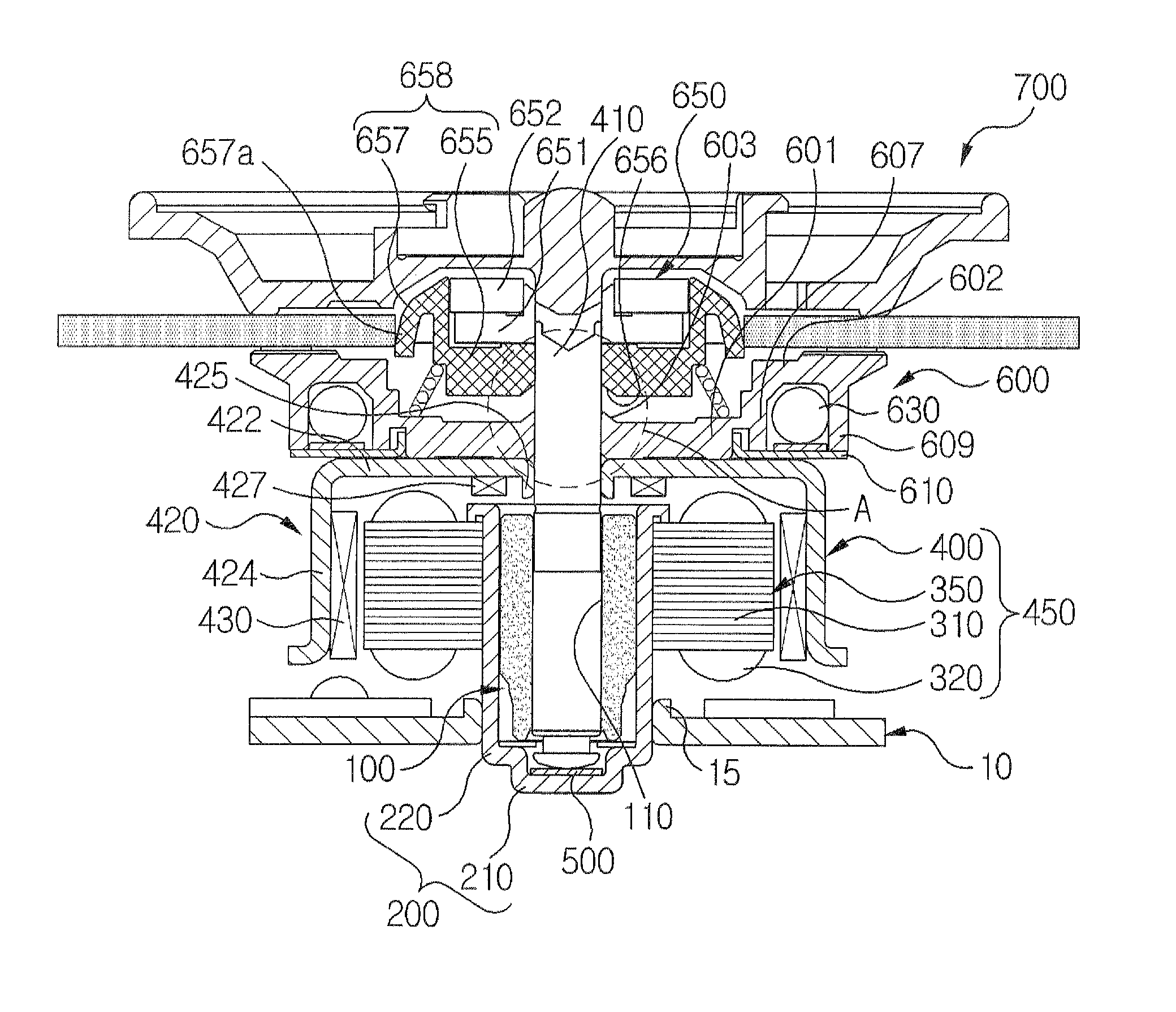
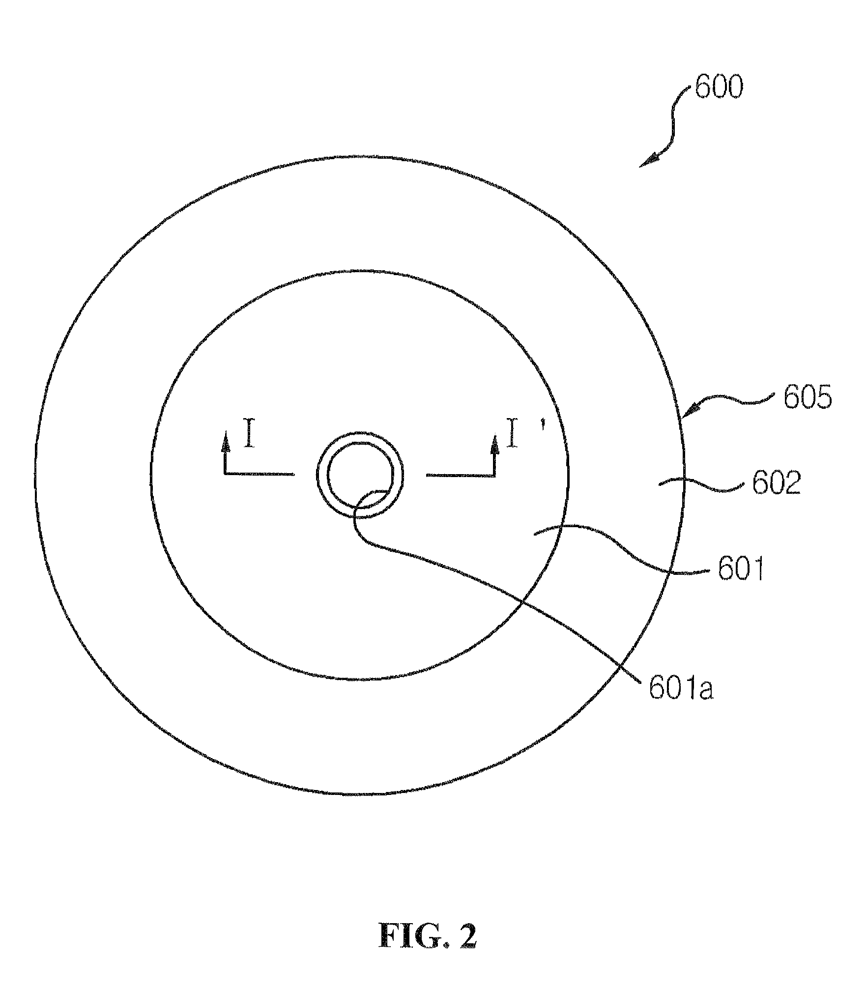
[0031]FIG. 1 is a sectional view showing a spindle motor in accordance with an exemplary embodiment of the present invention. FIG. 2 is a plan view showing a turntable of FIG. 1. FIG. 3 is a sectional view taken along line I-I′ of FIG. 2. FIG. 4 is an enlarged view showing portion ‘A’ of FIG. 1.

[0032]Referring to FIGS. 1 to 4, a spindle motor 700 includes a spindle motor...


PUM

PropertyMeasurementUnit
outer circumferenceaaaaaaaaaa
thicknessaaaaaaaaaa
lengthaaaaaaaaaa

Abstract

Disclosed is a spindle motor, the spindle motor including a rotating shaft, a turntable including a body into which a through hole is formed for coupling with the rotating shaft and which supports an optical disk and rotates along with the rotating shaft, and a centering unit which is fitted over the rotating shall, moves in an axial direction of the rotating shaft, and aligns a rotating center of the optical disk with a rotating center of the rotating shaft, wherein the turntable includes a reinforcing part that protrudes from the body along a periphery of the rotating shaft.

Description

CROSS-REFERENCE TO RELATED APPLICATION[0001]This application claims the benefit under 35 U.S.C. §119 of Korean Application No. 10-2010-0090341, filed Sep. 15, 2010, which is hereby incorporated by reference in its entirety.BACKGROUND OF THE INVENTION[0002]1. Field of the Invention[0003]The present invention relates to a spindle motor.[0004]2. Description of the Related Art[0005]Generally, an optical disk driver reads or records data from or in an optical disk. The optical disk driver includes a spindle motor that rotates the optical disk at a high speed, and an optical pickup module that stores data in a track of the optical disk rotating at a high speed and reads the data stored in the track of the optical disk.[0006]The spindle motor includes a turntable coupled to a rotating shaft to support an optical disk and a centering unit that aligns the rotating center of the optical disk with a rotating shaft.[0007]The turntable is press-fitted over the rotating shaft to rotate along with...

Claims


Application Information

Patent Timeline
Patent Type & Authority Patents(United States)
IPC IPC(8): G11B19/20
CPCH02K7/14G11B19/2009
Inventor KIM, YONGJOO
Owner HITACHI LG DATA STORAGE KOREA
Why Eureka
Try Eureka