Midfoot structure of a sole assembly for a shoe

a technology of sole assembly and midfoot, which is applied in the field of midfoot structure of a sole assembly for a shoe, to achieve the effects of improving contact feeling with the sole of the wearer's foot, hard to bend, and enhancing the shank

Active Publication Date: 2011-02-15
MIZUNO CORPORATION
View PDF19 Cites 56 Cited by
  • Summary
  • Abstract
  • Description
  • Claims
  • Application Information

AI Technical Summary

Benefits of technology

[0017]According to the first aspect of the present invention, since the midfoot outsole longitudinally separated from the outsole on the heel portion side and the outsole on the forefoot portion of the sole assembly is disposed at the midfoot portion of the sole assembly, the ground contact surface of the midfoot outsole contacts the ground when the shoe wearer strikes onto the ground from the heel portion of the sole assembly and the load is transferred toward the forefoot portion. At this juncture, since the lower midsole disposed under (i.e. on the side close to the ground) the midfoot portion has the upper surface of a downwardly convexedly curved shape to form the void with the upper plate, the lower plate can deform upwardly, thereby securing the cushioning properties of the midfoot portion. As a result, when the load is transferred from the heel portion through the midfoot portion to the forefoot portion, a smooth load transfer is made possible and a ride feeling during running can be improved.
[0027]If the hardness of the upper plate is greater than the hardness of the lower plate, when the load is applied to the midfoot portion, the lower plate of a relatively low hardness easily deforms upwardly to secure the cushioning properties and the upper plate of a relatively high hardness hardly deforms to enhance the support rigidity relative to the arch portion of the wearer's foot.

Problems solved by technology

However, this midfoot structure is not constructed such that the sole midfoot portion contacts the ground.

Method used


Image

  • Midfoot structure of a sole assembly for a shoe
  • Midfoot structure of a sole assembly for a shoe
  • Midfoot structure of a sole assembly for a shoe

Examples


Embodiment Construction

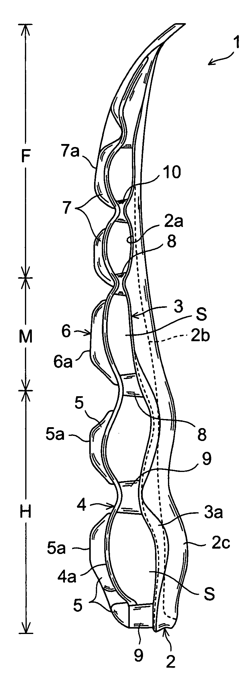
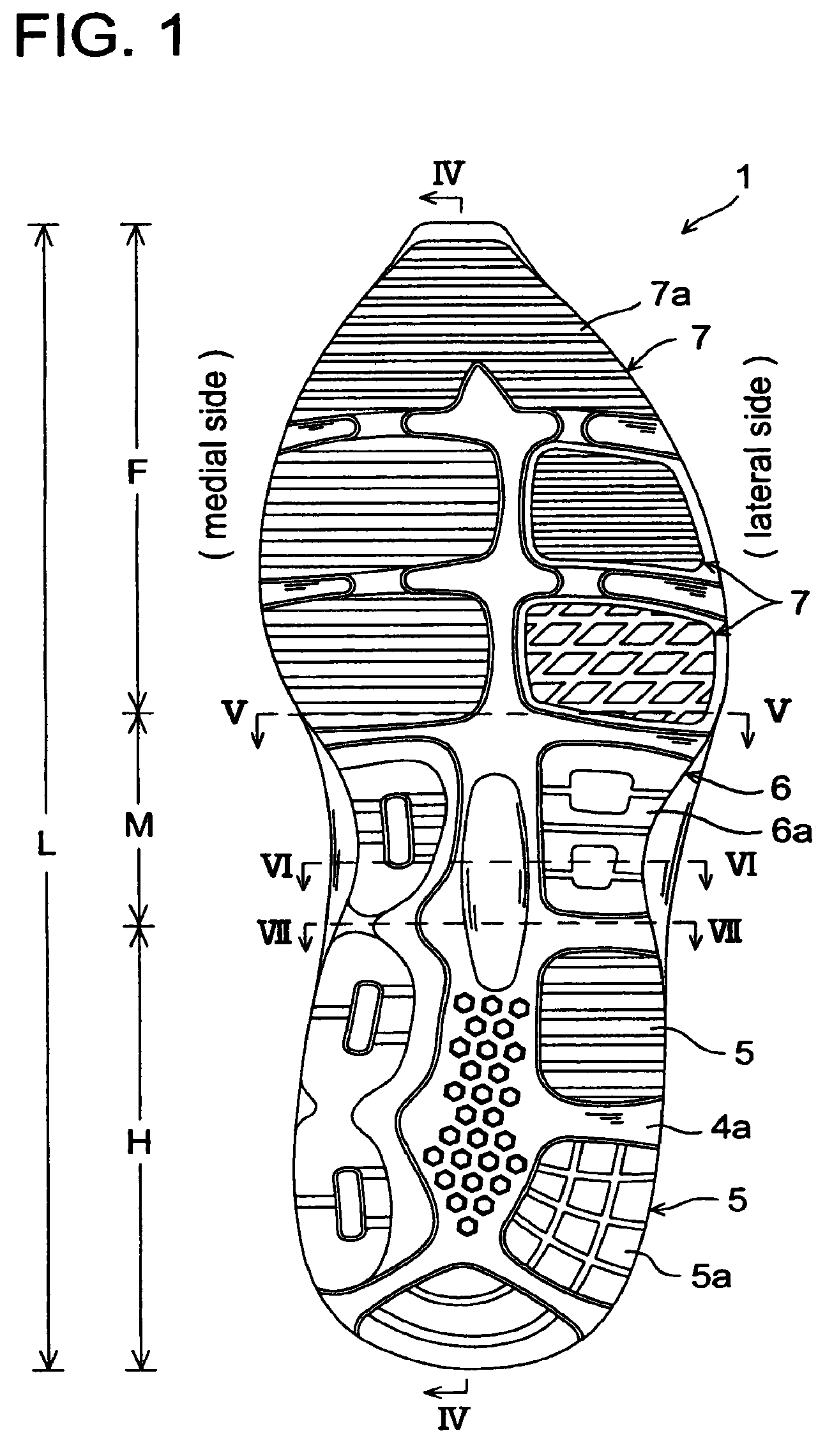
[0037]Referring now to the drawings, FIGS. 1 to 7 show a midfoot structure of a sole assembly for a shoe according to an embodiment of the present invention.

[0038]As shown in FIGS. 1 to 4, a sole assembly 1 is composed of a heel portion H, a midfoot portion M, and a forefoot portion F. The midfoot portion M is disposed in a region defined by 0.35 L to 0.55 L, measuring from the heel rear end edge of the sole assembly 1 or the bottom end edge of FIG.1, where L is the entire length of the sole assembly 1. Also, the rear end of the midfoot portion M or the boundary position relative to the heel portion H, is disposed in a position defined by 0.35 L to 0.45 L, measuring from the heel rear end edge of the sole assembly 1. The front end of the midfoot portion M or the boundary position relative to the forefoot portion F, is disposed in a position defined by 0.45 L to 0.55 L, measuring from the heel rear end edge of the sole assembly 1.

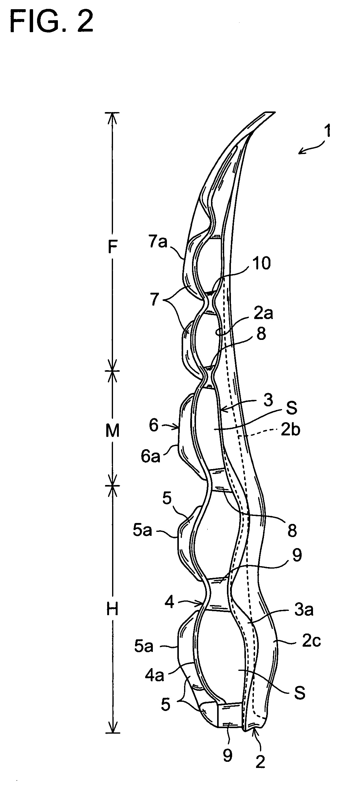
[0039]As shown in FIGS. 2 to 3, the sole assembly 1 in...


PUM


Abstract

A midsole structure of a sole assembly for a shoe improves a ride feeling and stability of the midfoot portion of the sole assembly during running. The sole assembly 1 of the shoe includes an upper plate 3 disposed on an upper side of a midfoot portion M and formed of a hard elastic member, a lower plate 4 disposed under the upper plate 3, wherein the lower plate is formed of a hard elastic member and has a downwardly convexedly curved shape that forms a void S relative to the upper plate, a midfoot outsole 6 attached on a bottom surface 4a of the lower plate 4, having a ground contact surface 6a, and provided discretely in the longitudinal direction from an outsole 5 of a heel portion H and an outsole 7 of a forefoot portion F of the sole assembly 1, and connections 8, 9 provided on front and rear ends of the midfoot portion M and interconnecting the upper plate 3 with the lower plate 4 in the vertical direction.

Description

BACKGROUND OF THE INVENTION[0001]The present invention relates generally to a midfoot structure of a sole assembly for a shoe, and more particularly, to an improvement in the structure for enhancing a ride feeling during running and improving stability of the midfoot portion of the shoe.[0002]Japanese patent application laying-open publication Nos. 2003-19004 and 2006-136715 show a midfoot structure of a sole assembly for a shoe.[0003]JP reference 2003-19004 describes a tubular or D-shaped plastic shank member that has a longitudinal length greater than the vertical length and that is disposed at the midfoot portion of a shoe. In this case, the shank member increases the bending rigidity of the midfoot portion to restrain the bending deformation of the midfoot portion, thereby relatively increasing the bending properties of the forefoot portion. Also, in this case, a void formed in the shank member improves the cushioning properties of the midfoot portion.[0004]JP reference 2003-190...

Claims


Application Information

Patent Timeline
Patent Type & Authority Patents(United States)
IPC IPC(8): A43B13/28A43B13/18
CPCA43B13/026A43B13/12A43B13/125A43B13/181A43B13/183A43B7/142A43B7/143A43B7/1445A43B7/1485A43B13/187A43B13/16
Inventor SATO, NATSUKI
Owner MIZUNO CORPORATION
Why Eureka
Try Eureka