Arrangement for recirculation of exhaust gases of a supercharged internal combustion engine

a supercharged internal combustion engine and exhaust gas technology, applied in the direction of combustion-air/fuel-air treatment, machines/engines, mechanical equipment, etc., can solve the problems of relative simplicity of arrangement close to the combustion engine, and insufficient course, etc., to achieve short and compact arrangement, easy to flow

Inactive Publication Date: 2011-02-15
SCANIA CV AB
View PDF40 Cites 5 Cited by
  • Summary
  • Abstract
  • Description
  • Claims
  • Application Information

AI Technical Summary

Benefits of technology

[0008]According to a preferred embodiment of the present invention, the arrangement comprises a second EGR cooler adapted to providing the recirculating exhaust gases in the return line with a second step of cooling after they have been cooled in the first EGR cooler. It is of course not sufficient merely to cool the exhaust gases in a first EGR cooler by means of compressed air when it is at such a high temperature. The recirculating exhaust gases are with advantage adapted to being cooled in the second EGR cooler by a medium which is at the temperature of the surroundings. With a suitably dimensioned EGR cooler it is therefore possible to cool the exhaust gases to a temperature close to the temperature of the surroundings.
[0009]According to another preferred embodiment of the present invention, the recirculating exhaust gases in the return line are adapted to being cooled in the second EGR cooler by the air in a portion of the inlet line which is situated upstream of the compressor. The second EGR cooler can therefore also be fitted in direct proximity to or on the combustion engine. The return line comprising two such EGR coolers can thus be made very short and compact so that the exhaust gases undergo only a very small pressure drop as they pass through the return line. With advantage, the air drawn into the inlet line is ambient air. Air at a temperature substantially corresponding to the temperature of the surroundings can thus be used for cooling the exhaust gases in the second EGR cooler.
[0010]According to another preferred embodiment of the invention, the arrangement comprises a charge air cooler adapted to cooling the compressed air in the inlet line to the combustion engine. The compressed air will be at a relatively high temperature after the compression. When it has been used for cooling the exhaust gases, the air will be at a still higher temperature. The amount of air which can be supplied to a supercharged combustion engine depends on the pressure and temperature of the air. In order to supply as large an amount of air as possible to the combustion engine, the compressed air needs to undergo effective cooling in the charge air cooler before it is led into the combustion engine. With advantage, the compressed air is adapted to being cooled in the charge air cooler by a medium which is at the temperature of the surroundings. The compressed air can thus be cooled to a temperature only a few degrees above the temperature of the surroundings. Said medium is preferably ambient air. Ambient air is suitable for the purpose since it is always available and can easily be caused to flow through the charge air cooler.
[0011]According to another preferred embodiment of the invention, the charge air cooler and a radiator for the combustion engine's cooling system are fitted in a common region through which ambient air flows. Such a region may be at a front portion of a vehicle which is powered by said combustion engine. Here a common radiator fan may be used for circulating ambient air through both the charge air cooler and the radiator. The charge air cooler is preferably fitted upstream of the radiator in said common region with respect to the direction of flow of the air. Ambient air thus flows through the charge air cooler before flowing through the radiator. There is thus assurance of the compressed air being cooled by air which is at the temperature of the surroundings, thereby making it possible to cool the compressed air to a temperature close to the temperature of the surroundings. The ambient air flowing through the radiator thereby acquires a somewhat higher temperature, but this temperature is sufficient for the coolant to undergo effective cooling in the radiator.

Problems solved by technology

It is therefore relatively uncomplicated to arrange close to the combustion engine such an EGR cooler which uses this already existing air flow in the inlet line downstream of the compressor in order to cool the exhaust gases in the return line.
It is of course not sufficient merely to cool the exhaust gases in a first EGR cooler by means of compressed air when it is at such a high temperature.

Method used


Image

  • Arrangement for recirculation of exhaust gases of a supercharged internal combustion engine
  • Arrangement for recirculation of exhaust gases of a supercharged internal combustion engine

Examples


Embodiment Construction

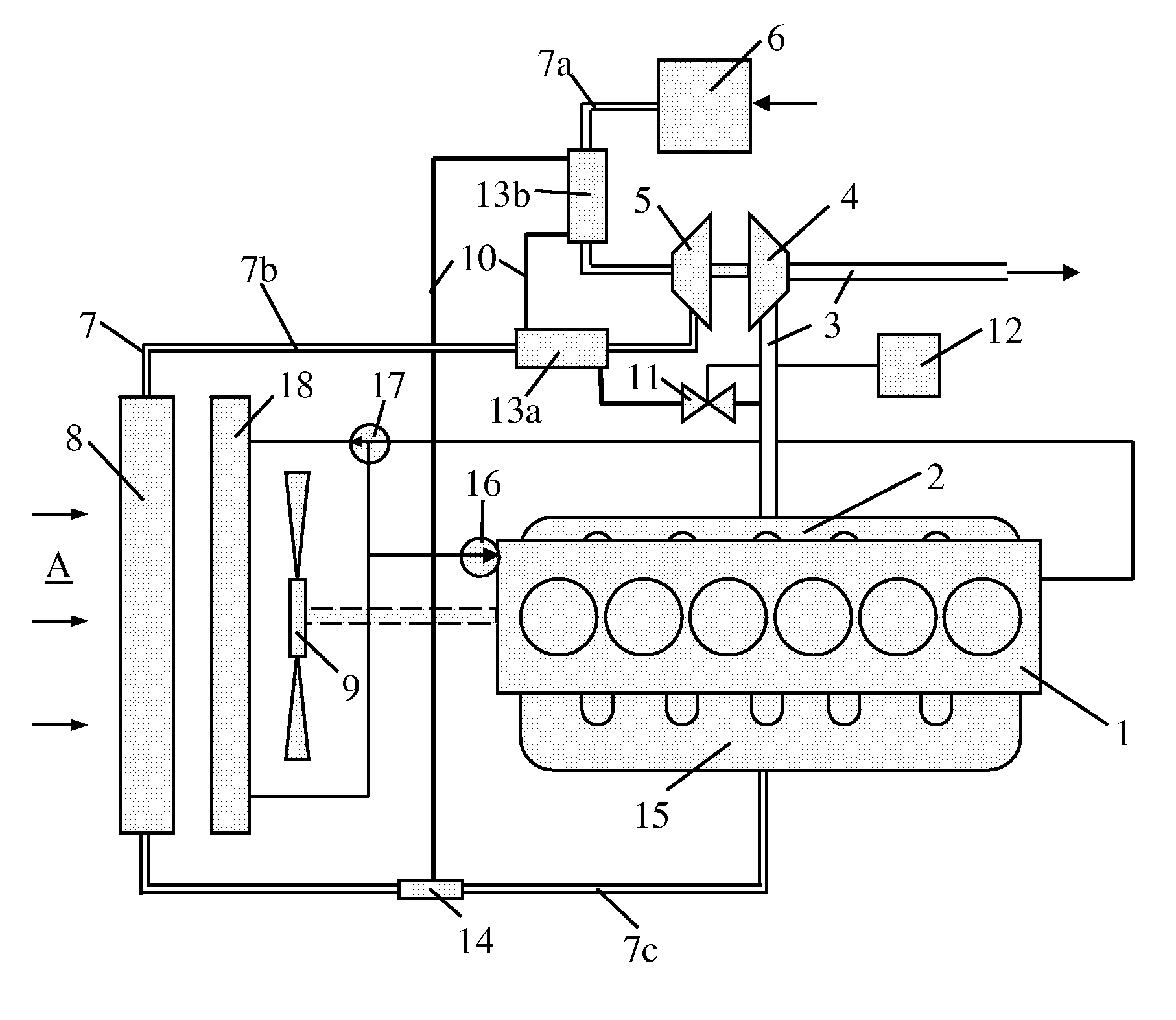
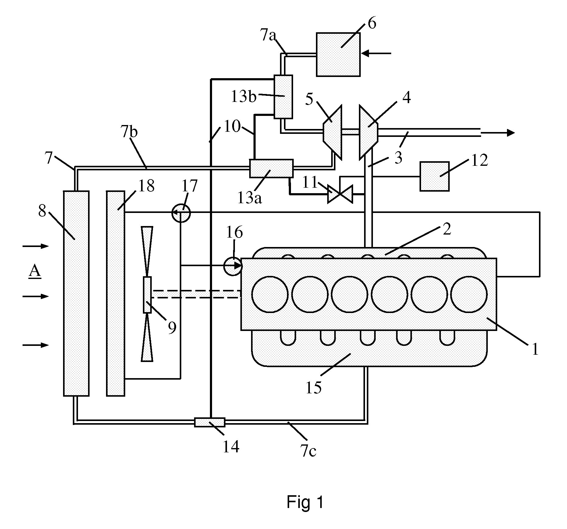
[0014]FIG. 1 depicts an arrangement for recirculation of exhaust gases of a supercharged combustion engine. The combustion engine in this case is a diesel engine 1. Such recirculation is usually called EGR (Exhaust Gas Recirculation). Adding exhaust gases to the compressed air which is led to the engine's cylinders lowers the combustion temperature and hence also the content of nitrogen oxides (NOx) formed during combustion processes. The diesel engine 1 may be intended to power a heavy vehicle. The exhaust gases from the cylinders of the diesel engine 1 are led via an exhaust manifold 2 to an exhaust line 3. The exhaust gases in the exhaust line 3, which are at above atmospheric pressure, are led to a turbine 4. The turbine 4 is thus provided with driving power which is transmitted, via a connection, to a compressor 5. Via an air filter 6, the compressor 5 draws ambient air into a first portion 7a of an inlet line 7. The air is compressed by the compressor 5, with the result that i...


PUM


Abstract

The present invention relates to an arrangement for recirculation of exhaust gases of a supercharged combustion engine. The arrangement comprises an exhaust line intended to lead exhaust gases out from the combustion engine, an inlet line intended to lead air which is at above atmospheric pressure to the combustion engine, a compressor adapted to the inlet line so that it is possible, via the return line, to recirculate exhaust gases from the exhaust line to the inlet line. The arrangement comprises a first EGR cooler in which the recirculating exhaust gases in the return line are cooled by the air in a portion of the inlet line which is situated downstream of the compressor in the inlet line with respect to the direction of flow of the air in the inlet line.

Description

CROSS REFERENCE TO RELATED APPLICATION[0001]The present application is a 35 U.S.C. §§371 national phase conversion of PCT / SE2006 / 050108, filed May 5, 2006, which claims priority of Swedish Patent Application No. 0501124-2, filed May 18, 2005, the disclosure of which has been incorporated herein by reference.BACKGROUND TO THE INVENTION, AND STATE OF THE ART[0002]The present invention relates to an arrangement for recirculation of exhaust gases of a supercharged combustion engine according to the preamble of claim 1.[0003]The technique known as EGR (Exhaust Gas Recirculation) is a known means of leading part of the exhaust gases from a combustion process in a combustion engine back, via a return line, to an inlet line for supply of air to the combustion engine. A mixture of air and exhaust gases is thus supplied via the inlet line to the engine's cylinders in which the combustion takes place. Adding exhaust gases to the air causes a lower combustion temperature which results inter ali...

Claims


Application Information

Patent Timeline
Patent Type & Authority Patents(United States)
IPC IPC(8): F02B47/08
CPCF02B29/0412F02B29/0425F02M25/073F02M31/08F02M25/0732F02M25/0707F02M25/0712Y02T10/126F02M25/0735Y02T10/121Y02T10/146F02M26/05F02M26/09F02M26/27F02M26/24F02M26/30Y02T10/12
Inventor KARDOS, ZOLTANWIKSTROM, HANS
Owner SCANIA CV AB
Why Eureka
Try Eureka