motor-driven machine tool

A motor-driven, machine tool technology, applied in the direction of manufacturing tools, metal processing equipment, sawing machine devices, etc., can solve problems such as susceptibility to interference

Inactive Publication Date: 2011-12-07
ROBERT BOSCH GMBH
View PDF8 Cites 2 Cited by
  • Summary
  • Abstract
  • Description
  • Claims
  • Application Information

AI Technical Summary

Problems solved by technology

Overall, this also leads to an overall length in the longitudinal direction of the lifting mast which is sometimes undesirable and can lead to a certain susceptibility to disturbances, especially under difficult operating conditions.
In particular, it is at least difficult to operate a power tool of this design in a pivoting lifting mode when the working tool is twisted around its longitudinal axis for a straight working direction.

Method used


Image

  • motor-driven machine tool
  • motor-driven machine tool
  • motor-driven machine tool

Examples


Embodiment Construction

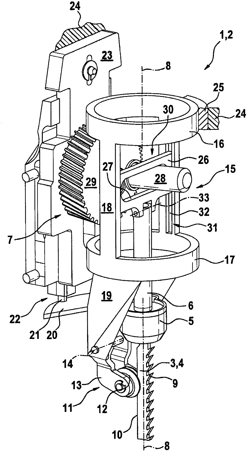
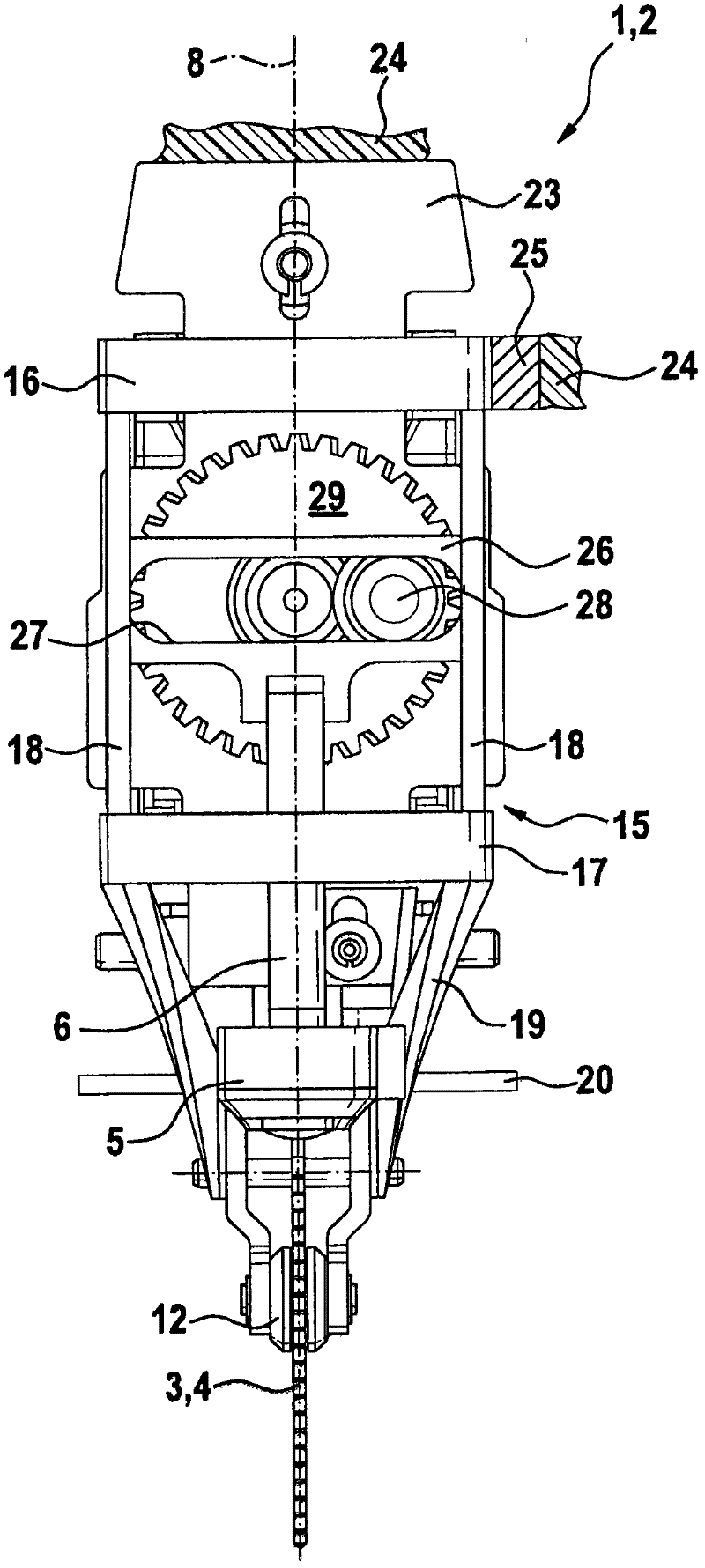
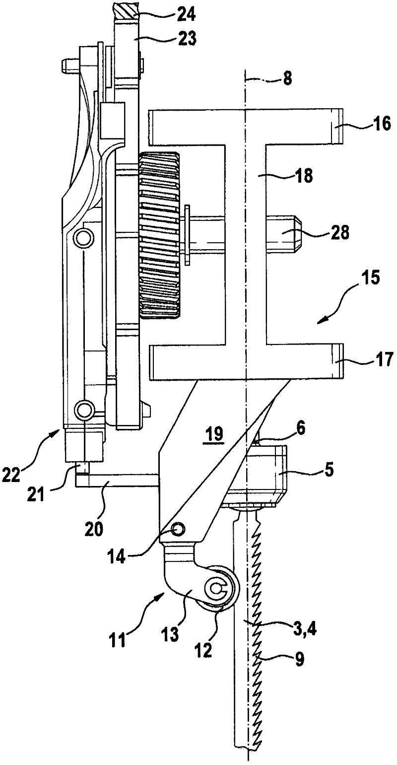
[0017] In these figures, a power tool 1 in the form of a jigsaw 2 is shown simplified and without housing, the working tool 3 of which is formed by a saw blade 4 driven in a lifting motion. The saw blade 4 is connected via a saw blade receiver 5 to a lifting rod 6 of a lifting drive 7 .

[0018] The saw blade 4 (as working tool 3 ) has a longitudinal axis 8 which lies in the working plane of the saw blade 4 . The saw blade is provided with a tooth structure 9 on the front, and the opposite saw blade is marked with 10 on the back. The support member 11 is supported on the saw blade back 10 via support rollers 12 . The support element 11 is formed by a rocker 13 , which is articulated via a pivot axis 14 to a support frame 15 .

[0019] The support frame 15 is cage-shaped and has an upper support ring 16 and a lower support ring 17 , between which two longitudinal struts 18 extend in the exemplary embodiment. Projecting downwards on the lower support ring 17 are two support l...


PUM


Abstract

Provided is a design scheme possessing a support frame (15) for a machine tool (1), especially for a machine tool (1) of which the conformation is a keyhole saw (2). The support frame (15)can be twistably supported on the housing and forms the guide structure for a linear sliding part (26) of the lifting drive unit (7) for the working tool (3), said linear sliding part (26) being mounted on the lifting rod.

Description

technical field [0001] The invention relates to a motor-driven power tool, in particular a hand power tool, according to the preamble of claim 1 . Background technique [0002] A motor-driven power tool of the aforementioned type is known from DE 37 02 670 A1. The power tool is relatively complex in its construction and has a lifting rod which is projected upwards by a lifting drive and is mounted at its upper end in a pivotable manner about an axis extending transversely to the working plane of the tool for pivoting. Lifting operation, the rotary drive for the lifting rod and the working tool connected to the lifting rod in a non-rotatable manner acts on the upper end. Overall, this also leads to an overall length in the longitudinal direction of the lifting mast that is sometimes undesirable and can lead to a certain susceptibility to interference, especially under difficult operating conditions. In particular, it is at least difficult to operate a power tool of this des...

Claims


Application Information

Patent Timeline
Patent Type & Authority Applications(China)
IPC IPC(8): B23D49/16
CPCB23D49/167
Inventor H·凯泽M·卡索塔
Owner ROBERT BOSCH GMBH
Why Eureka
Try Eureka