Implant-driver assembly

a technology for implants and drivers, applied in the field of medical implants, can solve the problems of implant manufacturers not being able to control the reuse of drivers by dental professionals, and implant manufacturers not being able to control whether an implant is touched prior to insertion, so as to avoid physically touching the implant and mitigate the effects of wear and unsuitability

Inactive Publication Date: 2011-02-15
KEYSTONE DENTAL INC
View PDF14 Cites 9 Cited by
  • Summary
  • Abstract
  • Description
  • Claims
  • Application Information

AI Technical Summary

Benefits of technology

[0005]This arrangement affords a number of advantages. The dental professional may grasp the assembly at the head of the driver or via the vial structure and thus may avoid physically touching the implant. Because the implant is provided to the dental professional with a driver, the dental professional will generally use the driver provided as part of the assembly, and will not reuse another driver, thus mitigating problems caused by worn or unsuitable drivers.
[0006]In another embodiment, a method is provided. The method includes providing an implant-driver assembly, inserting the implant into the jaw of a patient by imparting torque using the driver portion of the implant-driver assembly, and subsequently decoupling the driver and implant once the implant has been inserted into the jaw of the patient. The driver may be driven both clockwise and counterclockwise to thus provide the ability to adjust the depth of the implant in the jaw of the patient and specifically to withdraw the implant if it is inadvertently driven too deeply into the jaw.

Problems solved by technology

If the driver used for insertion of the implant is worn or is of poor quality, problems can result.
Implant manufacturers cannot control the reuse of drivers by dental professionals, even where suitable drivers are provided by the implant manufacturer.
Likewise, implant manufacturers cannot control whether an implant is touched prior to insertion.
Because the implant is provided to the dental professional with a driver, the dental professional will generally use the driver provided as part of the assembly, and will not reuse another driver, thus mitigating problems caused by worn or unsuitable drivers.

Method used


Image

  • Implant-driver assembly
  • Implant-driver assembly
  • Implant-driver assembly

Examples


Embodiment Construction

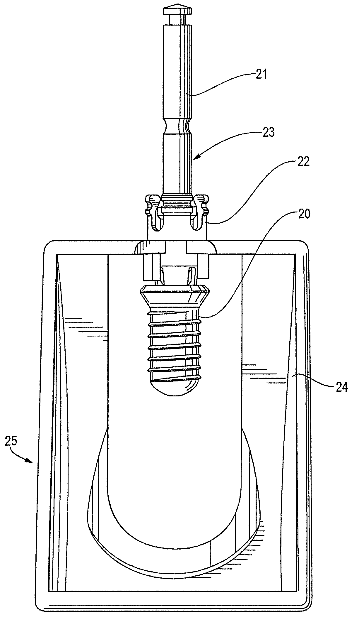
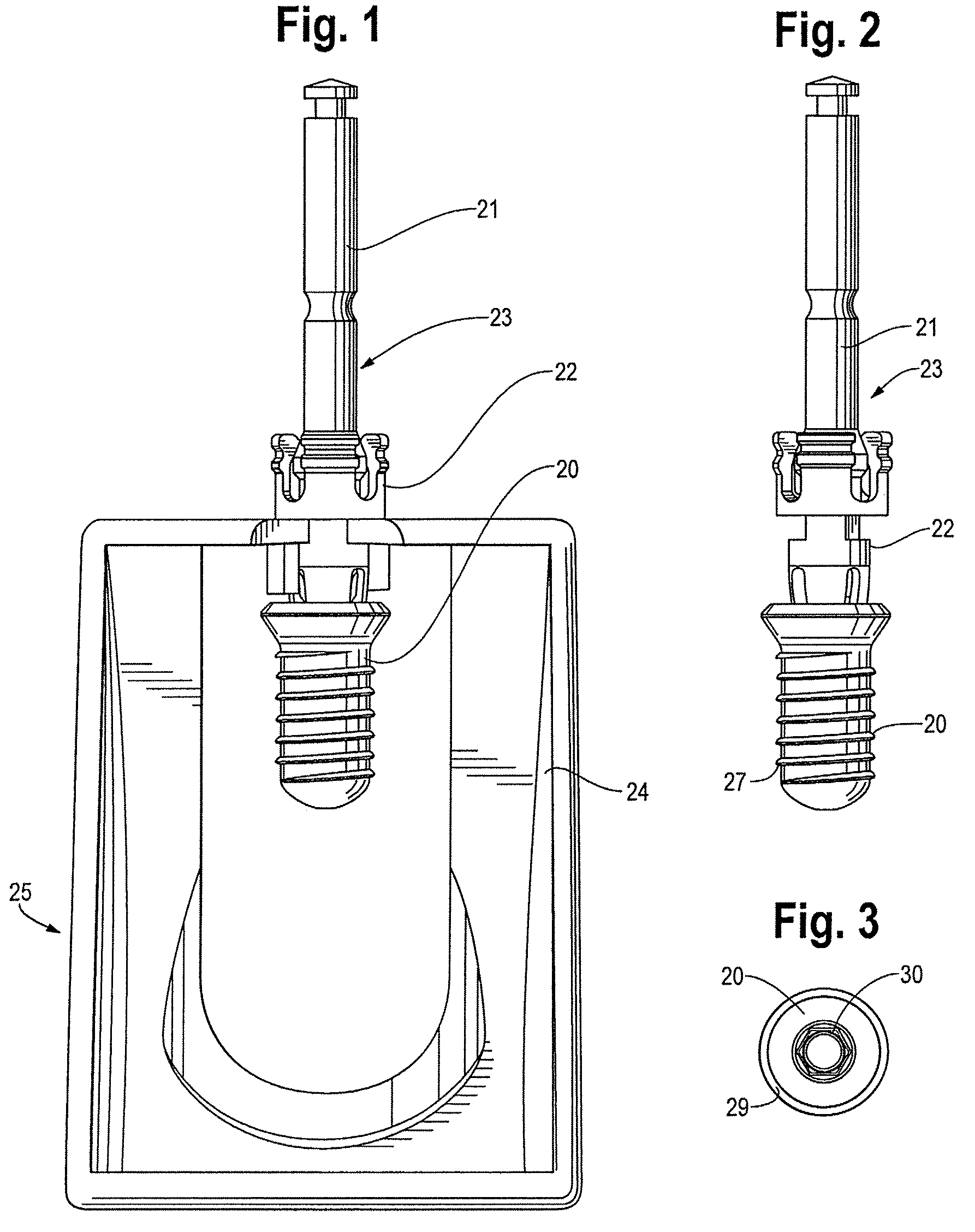
[0023]The implant-driver assembly may be provided to a dental professional in the form of a superassembly as illustrated in FIG. 1. With reference to FIGS. 1 and 2, the implant-driver assembly 23 includes an implant 20, a driver 21, and a coupler 22. The coupler is connected to the driver and to the implant as will be hereafter discussed, such that, during shipment and placement of the implant into the jaw of the patient, the driver 21 is fixed axially with respect to the implant 20. With reference to FIG. 1, a vial insert 24 is connected to the driver 21 and coupler 22 to prevent premature disengagement of the coupler 22 from the implant 20 and driver 21, as hereafter discussed in more detail, thus forming a superassembly 25. The superassembly 25 of FIG. 1 may be contained within an external shipping vial (not shown) for transport from the manufacture to a dental professional. The vial serves as a sterile barrier and shipping package. Upon receipt, the dental professional opens the...


PUM


Abstract

Disclosed are an implant-driver assembly and an associated method. Generally, the implant-driver assembly includes a driver, an implant and a coupler that affixes the implant to the driver during transport and during insertion of the implant into the jaw of a patient. As shipped, the assembly may take the form of a superassembly with a vial insert that impedes axial movement of the driver, coupler, and implant. Via manual action or assisted with a suitable tool, the coupler may be disengaged to thereby decouple the implant and driver once the implant has been properly positioned. Also disclosed is a method for inserting an implant, the method comprising applying torque to the driver of an implant-driver assembly as disclosed herein.

Description

TECHNICAL FIELD OF THE INVENTION[0001]The invention is in the field of medical implants, and in many embodiments is in the field of dental implants.BACKGROUND OF THE INVENTION[0002]Dental implants long have been known in the art. A dental implant is conventionally a screw-like structure that is threaded both externally and internally. Dental implants are used in the construction of artificial tooth structures in a patient who has lost one or several teeth. Conventionally, a bore is drilled into the jaw of a patient and the implant is driven into the bore. Implants conventionally are made of titanium or a titanium alloy, and, as is known in the art, the titanium implant will osseointegrate into the jaw of a patient over the course of the next several months. Thereafter, other structures are connected to the implant via the internal threads of the implant to form a prosthetic tooth or bridge. Typically, an abutment is connected to the implant via a threaded portion that engages the im...

Claims


Application Information

Patent Timeline
Patent Type & Authority Patents(United States)
IPC IPC(8): A61C3/00
CPCA61C8/0087A61C8/0089
Inventor WHIPPLE, DALE
Owner KEYSTONE DENTAL INC
Why Eureka
Try Eureka