Methods and apparatus of pressure imprint lithography

a technology of imprint lithography and imprinting, applied in the field of imprint lithography, can solve the problems of limited resolution, increased equipment cost, and difficulty in toleran

Inactive Publication Date: 2011-02-15
CHOU +1
View PDF4 Cites 17 Cited by
  • Summary
  • Abstract
  • Description
  • Claims
  • Application Information

AI Technical Summary

Problems solved by technology

In this approach, resolution is limited by the wavelength of the radiation, and the equipment becomes increasingly expensive as the feature size becomes smaller.
The use of a high precision mechanical press to press a mold into a thin film presents tolerance problems in replicating small patterns over large areas.
Such spacings permit undesirable relative translational and rotational shifts between the substrate and the mold.
Moreover, despite the most careful construction, the molds and the substrates used in lithography are not perfectly planar.
When these molds and substrates are disposed on the rigid plates of a press, the deviations from planarity over large areas can result in variations in the molding pressure and depth of imprint.

Method used


Image

  • Methods and apparatus of pressure imprint lithography
  • Methods and apparatus of pressure imprint lithography
  • Methods and apparatus of pressure imprint lithography

Examples


Embodiment Construction

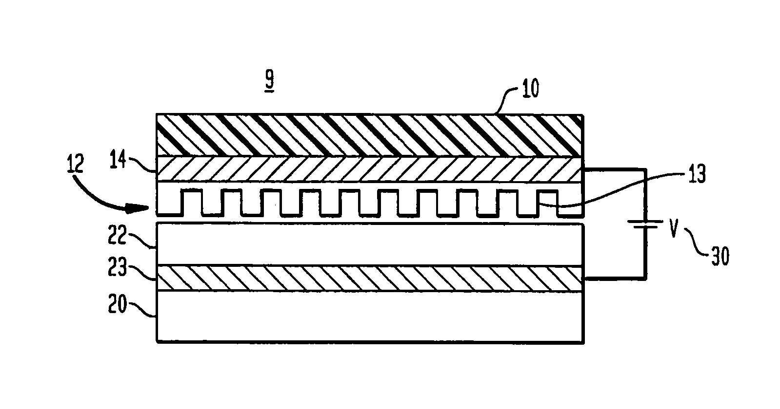
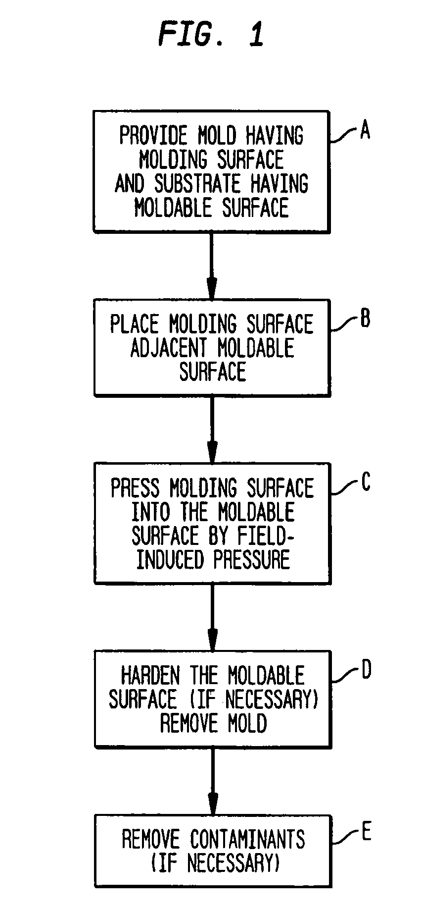
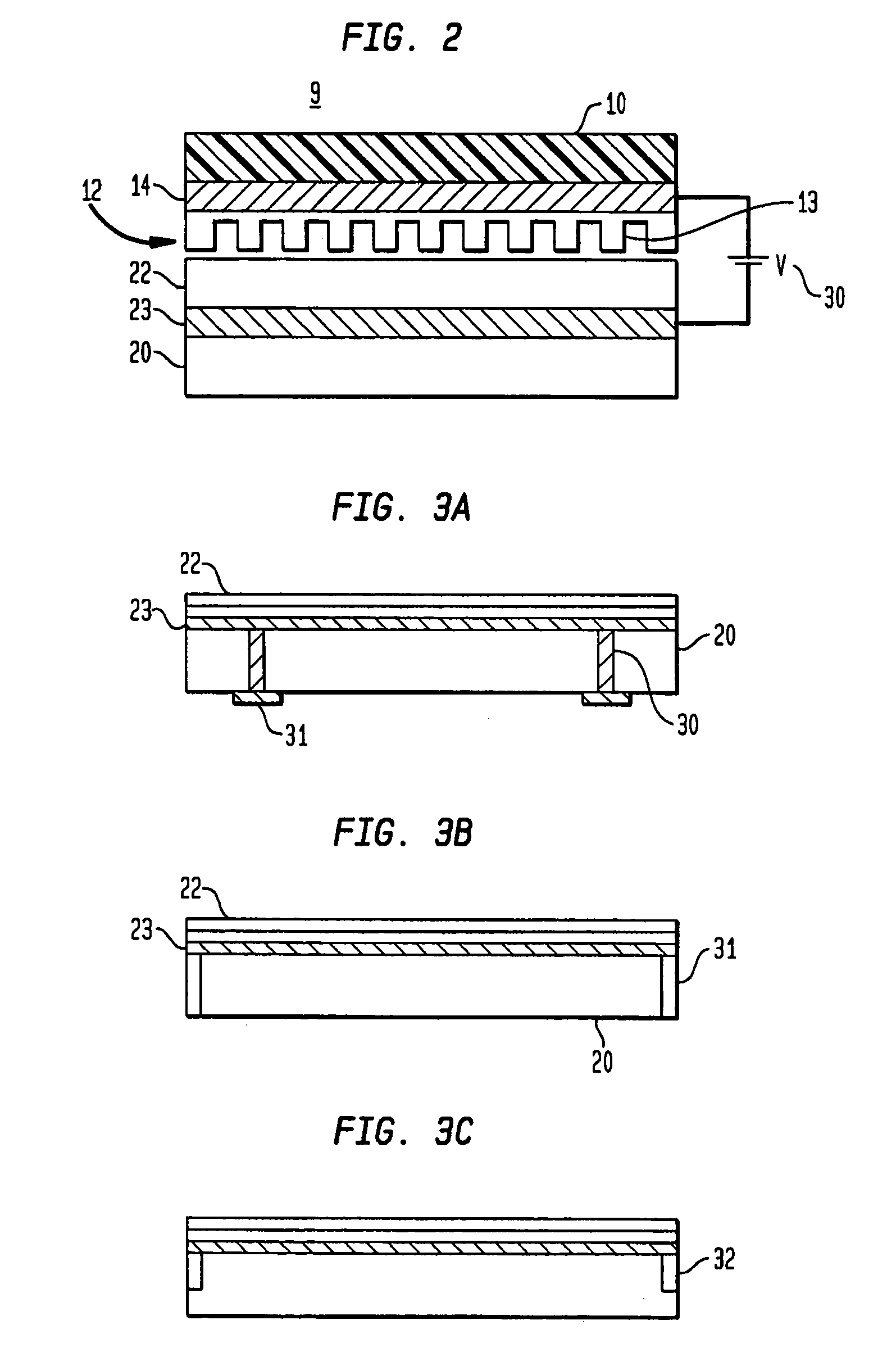
[0024]Referring to the drawings, FIG. 1 is a schematic flow diagram of an improved process for imprint lithography using field-induced pressure. An initial step shown in Block A, is to provide a mold having a molding surface such as plurality of protruding features and a substrate having a surface of moldable material such as one or more moldable thin films. Protruding features are preferably micrometer scale features and, more advantageously, nanoscale features. The method is highly advantageously where the mold surface has at least two spaced apart protruding features. A moldable material is one which retains or can be hardened to retain the imprint of the protruding features from the mold surface.

[0025]The next step, shown in Block B, is to place the mold adjacent the moldable surface. If the moldable surface is a thin film that already includes a previously formed pattern, then the pattern of the mold should be carefully aligned with the previous pattern. This can be done by ali...


PUM

PropertyMeasurementUnit
thicknessaaaaaaaaaa
moldableaaaaaaaaaa
conductiveaaaaaaaaaa

Abstract

An improved method of imprint lithography involves using fluid-induced pressure from electric or magnetic fields to press a mold onto a substrate having a moldable surface. In essence, the method comprises the steps of providing a substrate having a moldable surface, providing a mold having a molding surface and pressing the molding surface and the moldable surface together by electric or magnetic fields to imprint the molding surface onto the moldable surface. The molding surface advantageously comprises a plurality of projecting features of nanoscale extent or separation, but the molding surface can also be a smooth planar surface, as for planarization. The improved method can be practiced without mechanical presses and without sealing the region between the mold and the substrate.

Description

CROSS-REFERENCE TO RELATED APPLICATIONS[0001]This application is a continuation of U.S. patent application Ser. No. 10 / 445,578 filed by Stephen Y. Chou, et al. on May 27, 2003.[0002]The '578 patent claims the benefit of U.S. Provisional Patent Application Ser. No. 60 / 382,961 filed by Stephen Y. Chou and Wei Zhang on May 24, 2002 and entitled “Field-Induced Pressure Imprint Lithography”.[0003]The '578 application is also a continuation-in-part of U.S. patent application Ser. No. 10 / 244,276 filed by Stephen Chou on Sep. 16, 2002 and entitled “Lithographic Method For Molding Pattern With Nanoscale Features” which, in turn, is a continuation of U.S. application Ser. No. 10 / 046,594 filed by Stephen Y. Chou on Oct. 29, 2001, is a divisional of, and claims priority to U.S. patent application Ser. No. 09 / 107,006 filed by Stephen Y. Chou on Jun. 30, 1998 (now U.S. Pat. No. 6,309,580 issued Oct. 30, 2001) and which, is a continuation of, and in turn, claims priority to U.S. application Ser. N...

Claims


Application Information

Patent Timeline
Patent Type & Authority Patents(United States)
IPC IPC(8): B29C43/36B29C43/56B29C43/02G03F7/00
CPCB29C33/62B29C43/003B29C43/021B29C43/36B29C43/56B29C59/022B82Y10/00B82Y40/00G03F7/0002G03F9/7053B29C43/52B29C59/026B29C2043/025B29C2043/3211B29C2043/568B29C2059/023
Inventor CHOUZHANG, WEI
Owner CHOU
Why Eureka
Try Eureka