Driver circuit for a two-wire conductor and method for generating two output currents for a two-wire conductor

a two-wire conductor and drive circuit technology, applied in logic circuit coupling/interface arrangement, data switching network, baseband system details, etc., can solve the problems of large space, weight and cost, and inability to achieve a satisfactory common mode respons

Active Publication Date: 2011-02-15
INFINEON TECH AG
View PDF17 Cites 8 Cited by
  • Summary
  • Abstract
  • Description
  • Claims
  • Application Information

AI Technical Summary

Benefits of technology

[0005]The method for generating two complementary output currents from a two-state logic input signal at two outputs includes the steps: generating from the input signal an output signal at each output, the amperage of one of the output currents being adjustable by a control signal; analyzing each voltage materializing at the outputs; generating an error signal as a function of the output voltages within each of at least two time slots subsequent to a change in state of the input signal; caching the error signals or signals derived therefrom and adjusting, as a function of cached error signals or of the cached signals as a function thereof, the output current of the one output stage in corresponding time slots subsequent to a resulting change in state of the input signal.

Problems solved by technology

Although passive common mode chokes are often employed for a good common mode response, they are at a great disadvantage as to the required space, weight and costs involved.
Despite active circuit assemblies also being known to improve the common mode response of driver circuits they are hampered by being unstable in not always achieving a satisfactory common mode response.

Method used


Image

  • Driver circuit for a two-wire conductor and method for generating two output currents for a two-wire conductor
  • Driver circuit for a two-wire conductor and method for generating two output currents for a two-wire conductor
  • Driver circuit for a two-wire conductor and method for generating two output currents for a two-wire conductor

Examples


Embodiment Construction

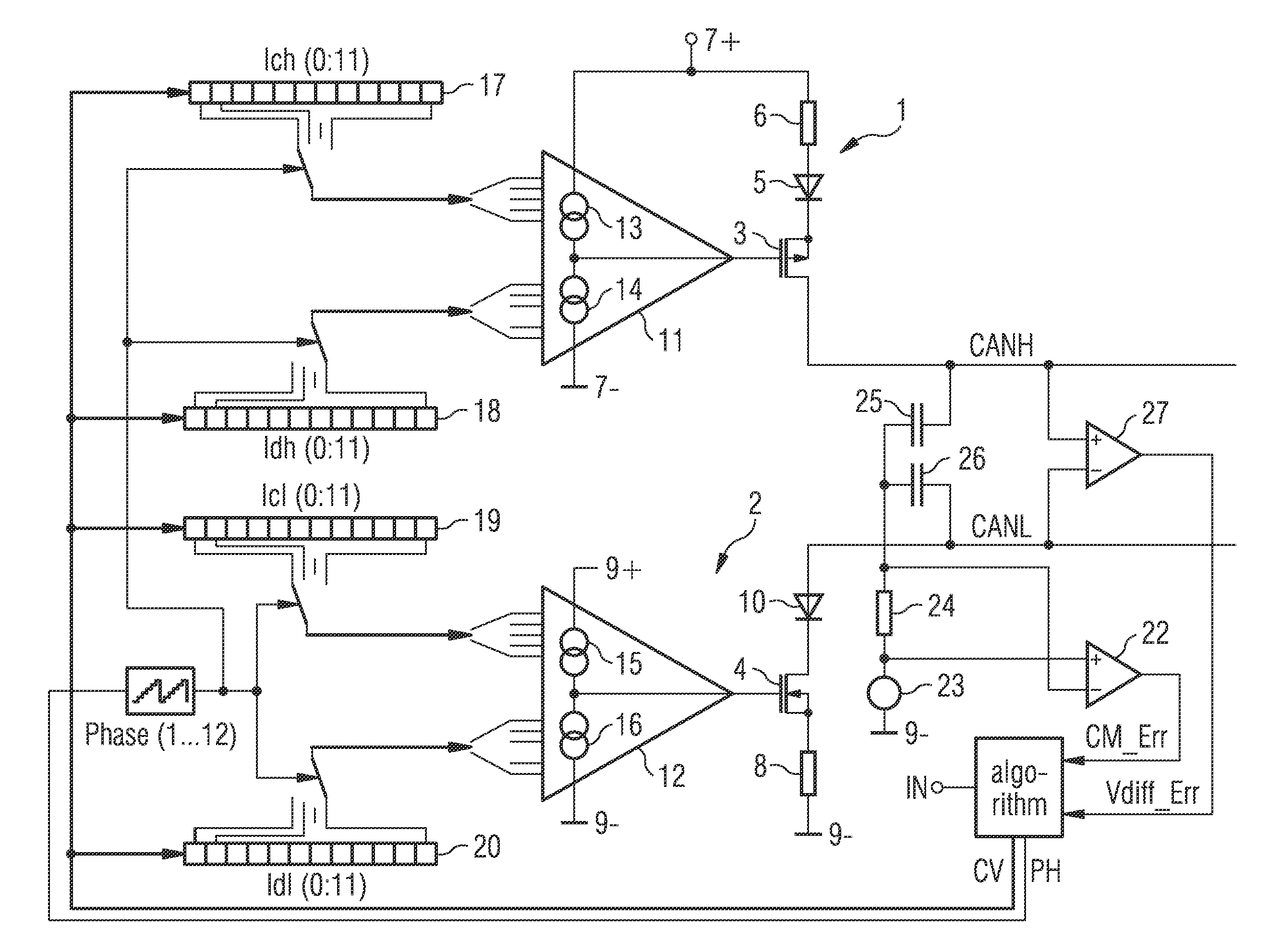
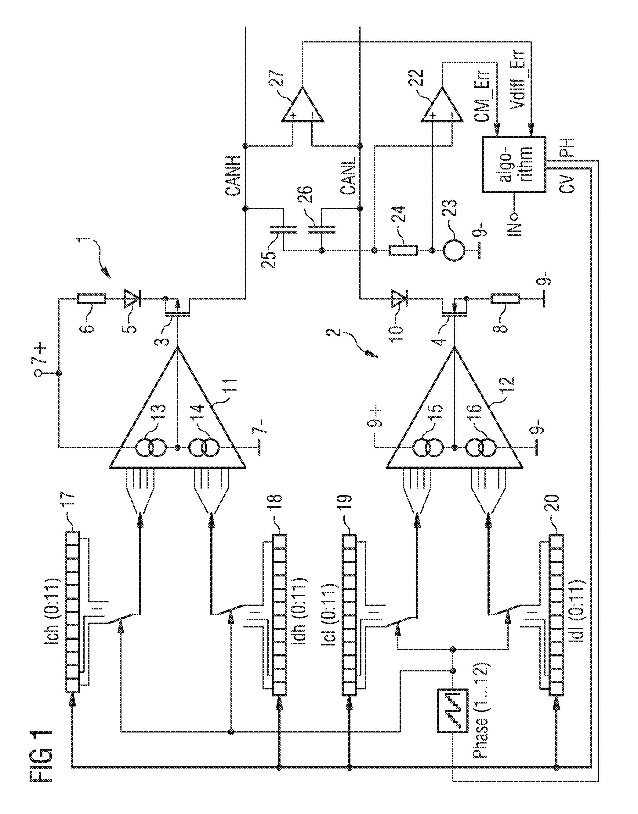
[0016]FIG. 1 illustrates a circuit diagram of a novel circuit assembly for activating a two-wire conductor with two complementary output currents CANH and CANL as a function of an input signal IN. The circuit assembly comprises two output stages 1, 2, output stage 1 furnishing the output signal CANH and the other output stage 2 the output signal CANL, each of which is connected to a positive supply potential 7+ and 9+ respectively as well as GND 7− and 9− respectively. Each of the two output stages 1 and 2 includes a (metal) field-effect transistor 3 and 4 respectively, the transistor 3 being a p-channel type and transistor 4 an n-channel type. Instead of field-effect transistors it is possible that bipolar transistors can be used. The source of the transistor 3 is connected via a diode 5 in the FWD direction and in series therewith a resistor 6 is connected to a positive supply potential 7+. The drain of the transistor 3 furnishes the output signal CANH. The source of transistor 4 ...


PUM


Abstract

A driver circuit and method for generating two complementary output currents from a two-state logic input signal at two outputs for connecting a two-wire conductor provide the following actions: generating from the input signal, an output signal at each output, the amperage of one of the output currents being adjustable by a control signal; analyzing each voltage materializing at the outputs; generating an error signal as a function of the output voltages within each of at least two time slots subsequent to a change in state of the input signal; caching the error signals or signals derived therefrom and adjusting, as a function of cached error signals or of the cached signals as a function thereof, the output current in corresponding time slots subsequent to a resulting change in state of the input signal.

Description

[0001]This application claims priority to German Patent Application 10 2009 000 697.4, which was filed Feb. 6, 2009 and is incorporated herein by reference.TECHNICAL FIELD[0002]The invention relates to a driver circuit for a two-wire conductor for generating two complementary output currents from a two-state logic input signal and to a method for generating two complementary output currents at two outputs for a two-wire conductor from a two-state logic input signal.BACKGROUND[0003]Two-wire conductors operated with complementary currents find an application particularly in bus systems designed for optional extension and / or lengthy conductors as is the case, for example, in a universal serial bus (USB) or in a controller area network bus (CAN bus). The signals to be communicated are fed into the two-wire conductor by means of a special driver circuit necessitating compliance especially with regards to electrostatic discharge (ESD), electromagnetic interference (EMI), electromagnetic c...

Claims


Application Information

Patent Timeline
Patent Type & Authority Patents(United States)
IPC IPC(8): H03K19/0175
CPCH04B3/06H04L25/028H04L12/40169H04L2012/40215
Inventor METZNER, DIETERPIHET, ERIC
Owner INFINEON TECH AG
Why Eureka
Try Eureka