
Liquid crystal display device appreciating room

a technology of liquid crystal display and appreciating room, which is applied in non-linear optics, instruments, optics, etc., can solve the problems of insufficient advantage and restrictive glare prevention on the screen, and achieve small advantage, prevent glare, and maintain the brightness of the inside of the room

Inactive Publication Date: 2011-02-15
NITTO DENKO CORP
View PDF5 Cites 9 Cited by
  • Summary
  • Abstract
  • Description
  • Claims
  • Application Information

AI Technical Summary

Benefits of technology

The present invention provides a liquid crystal display device that can prevent glare and external-image-projection on the screen while still being bright. This is achieved by using a special ¼ wavelength plate that converts circularly polarized light to linearly polarized light, which is then absorbed into the viewing-side polarizer of the liquid crystal panel. The device also includes a lighting apparatus that emits circularly polarized light. The invention can be used in a room where the liquid crystal display device is placed, and the room should have fine irregularities on the front surface of the ¼ wavelength plate for optimal results. The lighting apparatus can be a natural light source or a light emitting unit. The optical member can also have a film exhibiting a cholesteric phase.

Problems solved by technology

Thus, it is restrictive to prevent glare on the screen of a liquid crystal panel.
As a result, a sufficient advantage cannot be expected.
However, when plural persons watch the television at the same time, the advantage of preventing glare for all of the persons cannot be expected.

Method used


Image

  • Liquid crystal display device appreciating room
  • Liquid crystal display device appreciating room
  • Liquid crystal display device appreciating room

Examples


Embodiment Construction

[0024]With reference to the attached drawings, the present invention will be specifically described hereinafter.

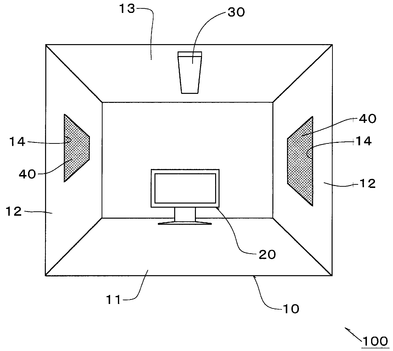
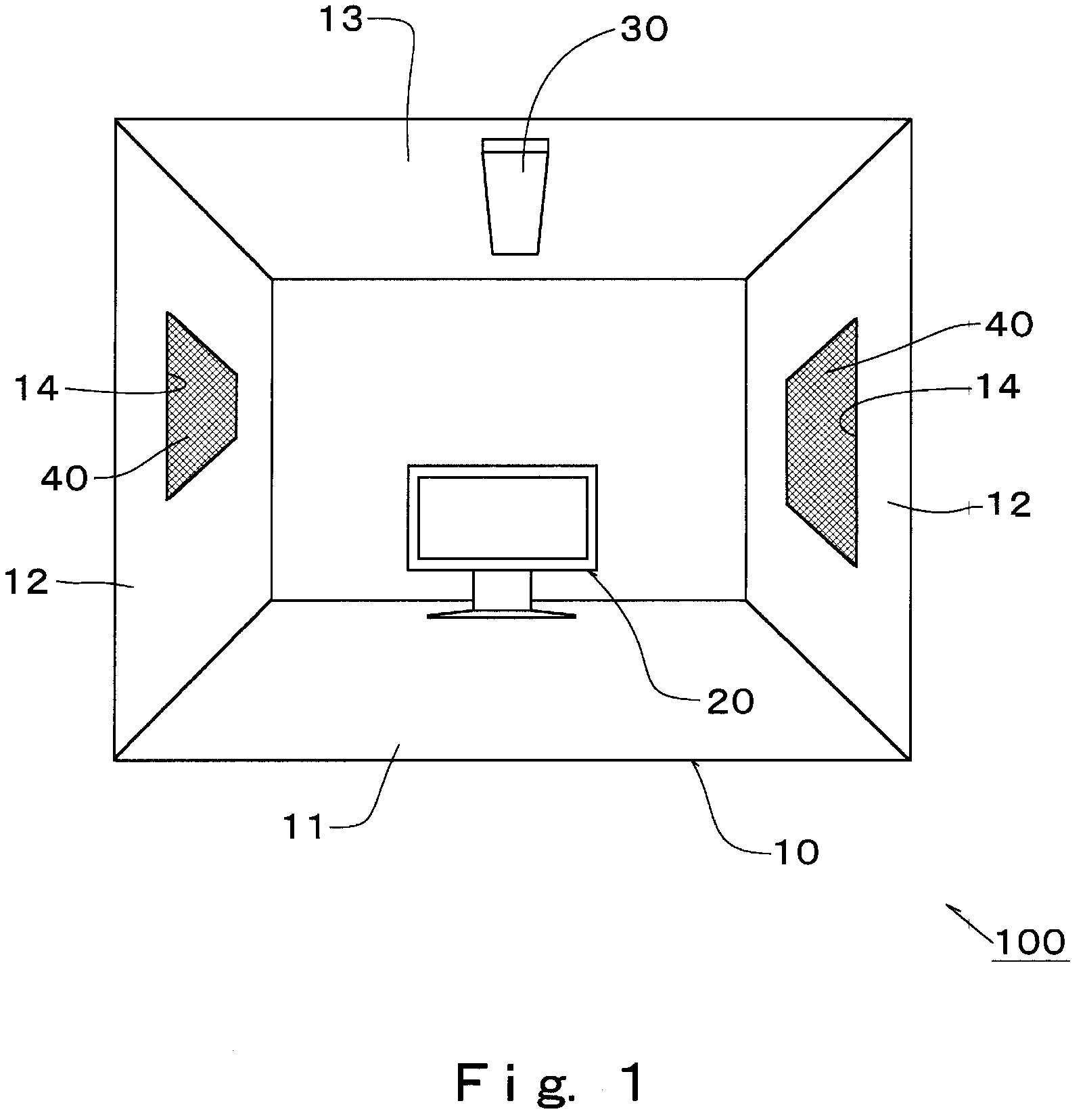
[0025]FIG. 1 is a reference view which schematically illustrates a liquid crystal display device appreciating room 100 of the present invention arranged in a building.

[0026]The liquid crystal display device appreciating room 100, which may be referred to merely as the “appreciating room” hereinafter, has a room 10 having therein a space, a liquid crystal display device 20 arranged in the space, and a light source which lightens the inside of the room.

[0027]The space of the room 10 is a space in which one or more persons watch the liquid crystal display device. The room may be, for example, a room in a building. The room 10 in the building is composed of, for example, a floor plane 11, wall planes 12 and a ceiling plane 13, which are structures. Openings (windows) 14 for taking in light outside the room (i.e., outdoor light) are made in portions of the wall planes 12 (and / o...


PUM

PropertyMeasurementUnit
angleaaaaaaaaaa
angleaaaaaaaaaa
wavelengthaaaaaaaaaa

Abstract

Provided is a liquid crystal display device appreciating room making it possible to prevent glare or external-image-projection on the basis of external light so that persons can watch the screen of a liquid crystal display device satisfactorily. The appreciating room comprises a room, a liquid crystal display device arranged inside the room and having a liquid crystal panel 2, and a light source which lightens the inside of the room, wherein a ¼ wavelength plate 6 is arranged on the front surface side of a viewing-side polarizer 3 of the liquid crystal panel 2, the ¼ wavelength plate 6 is arranged to set the angle θ of the slow axis direction X thereof to 45±5° or 135±5° from the absorptive axis direction A of the viewing-side polarizer toward the counterclockwise direction when the ¼ wavelength plate is seen from the viewing-side, and light inside the room is any one of left-handed circularly polarized light and right-handed circularly polarized light.

Description

FIELD OF THE INVENTION[0001]The present invention relates to a liquid crystal display device appreciating room making it possible to prevent glare on the display surface of a liquid crystal display device, or reflection inside the device.DESCRIPTION OF THE RELATED ART[0002]Liquid crystal display devices are widely used in notebook-size personal computers, mobile phones, televisions, large-sized display devices for home theater systems, and other articles. In recent years, liquid crystal display devices have been frequently used in relatively large-sized televisions having a screen 30 inches or more in size.[0003]The liquid crystal panel of such liquid crystal display devices is generally equipped with at least a backside polarizer, a liquid crystal cell wherein a liquid crystal material is injected into a gap between a pair of liquid crystal cell substrates, and a viewing-side polarizer, which are arranged in this order from the side of a back light.[0004]Incidentally, when a liquid...

Claims


Application Information

Patent Timeline
Patent Type & Authority Patents(United States)
IPC IPC(8): G02F1/13
CPCG02F1/13363G02F2001/133638G02F2413/12G02F2413/08G02F2413/02G02F1/133638G02F1/1333
Inventor YOSHIMI, HIROYUKIKITAGAWA, TAKEHARU
Owner NITTO DENKO CORP
Learn More