Interferometer for quantitative phase contrast imaging and tomography with an incoherent polychromatic x-ray source

Active Publication Date: 2011-02-15
PAUL SCHERRER INSTITUT
View PDF5 Cites 114 Cited by
  • Summary
  • Abstract
  • Description
  • Claims
  • Application Information

AI Technical Summary

Benefits of technology

[0012]It is the object of the present invention to provide an apparatus for phase contrast x-ray images which does

Problems solved by technology

Although some of them yield excellent results for specific problems, none is very widely used.
In particular, none of them has so far found medical diagnostics applications, which require a large field of view of many centimeters, the efficient use of broadband radiat

Method used


Image

  • Interferometer for quantitative phase contrast imaging and tomography with an incoherent polychromatic x-ray source
  • Interferometer for quantitative phase contrast imaging and tomography with an incoherent polychromatic x-ray source
  • Interferometer for quantitative phase contrast imaging and tomography with an incoherent polychromatic x-ray source

Examples


Embodiment Construction

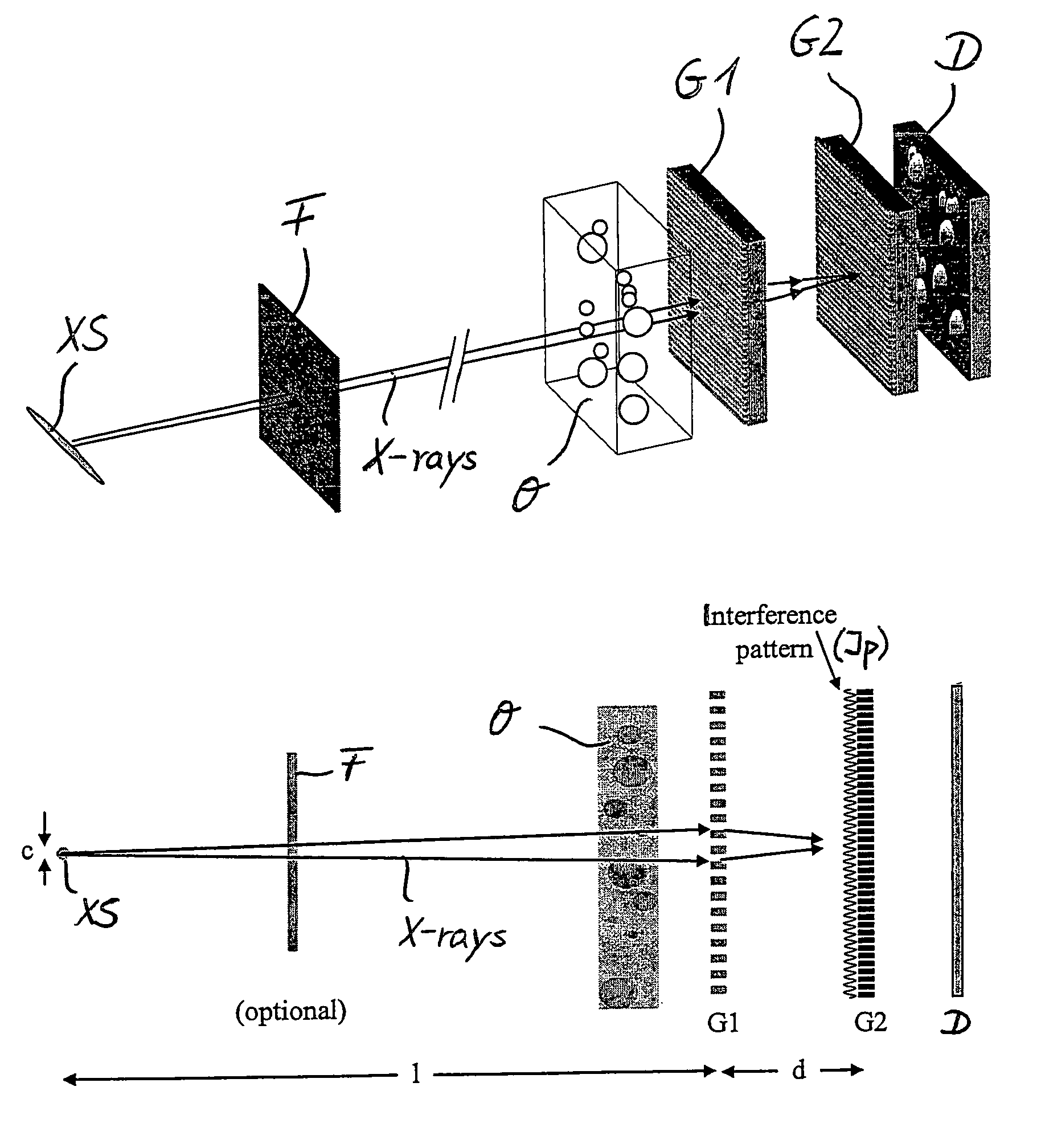
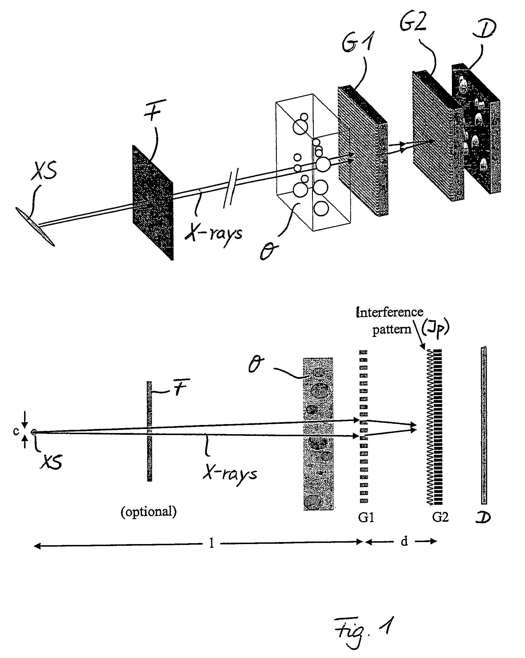
[0044]The basis of the present invention is the two-grating interferometer as it is shown in FIG. 1. It comprises the following components: an x-ray source XS (e.g. a stationary or rotating anode with a typical electron energy in the range of 10 to 100 keV, or any other X-ray source), an optional set of appropriate filters F, an object O, a beam splitter phase grating G1, an analyzer amplitude grating G2, and a spatially resolving x-ray detector D. The source XS provides some degree of spatial coherence at least in one direction perpendicular to the optical axis A. If the source is an X-ray tube, then the anode material should be chosen to have appropriate lines in the energy range well suited for the specific application. For mammography these could be Nb, Mo, Rh, Pd, Ag, which have K-emission lines in the 15 to 25-keV region. For other applications with thinner or less absorbing samples (e.g. desktop tomography setups) the energy would be in the range of 5-10 keV (e.g. a Cu anode)...


PUM


Abstract

An interferometer for X-rays, in particular hard X-rays, for obtaining quantitative phase contrast images, includes a standard polychromatic X-ray source, a diffractive optical beam splitter other than a Bragg crystal in transmission geometry, and a position-sensitive detector with spatially modulated detection sensitivity.

Description

CROSS-REFERENCE TO RELATED APPLICATIONS[0001]The present application is a national stage application of International Application No. PCT / EP2006 / 005119, filed on May 30, 2006, which claims priority to European Patent Application No. 05012121.9, filed on Jun. 6, 2005, both of which are incorporated herein by reference.BACKGROUND OF THE INVENTION[0002]The present invention relates to an interferometer for X-rays, in particular hard X-rays, for obtaining quantitative phase contrast images and measuring wavefront shapes.[0003]For hard X-rays, the cross section for absorption, which generates the contrast in conventional radiography, is usually much smaller than that for elastic scattering. The elastic scattering causes a phase shift of the wave passing through matter. If, for example, 17.5-keV x-rays (which are commonly applied for mammography) pass through a 50-μm-thick sheet of biological tissue, the attenuation will only be a fraction of a percent, while the phase shift is close to π...

Claims


Application Information

Patent Timeline
IPC IPC(8): G03H5/00
CPCA61B6/4233A61B6/484A61B6/4291G01N23/04A61B6/06G21K2207/005A61B6/4092A61B6/502G01N23/041
Inventor DAVID, CHRISTIANPFEIFFER, FRANZWEITKAMP, TIMM
Owner PAUL SCHERRER INSTITUT
Why Eureka
Try Eureka