Medical image diagnosis support device and method for calculating degree of deformation from normal shapes of organ regions

a technology of supporting device and imaging image, which is applied in the field of medical image diagnosis support device for supporting image diagnosis, can solve the problems of imposing strain on the subject and taking a long time to perform an examination on each patient, and achieve the effect of improving the efficiency of diagnosis

Active Publication Date: 2011-02-22
FUJIFILM HEALTHCARE CORP
View PDF10 Cites 34 Cited by
  • Summary
  • Abstract
  • Description
  • Claims
  • Application Information

AI Technical Summary

Benefits of technology

[0012]The above-mentioned device enables selective diagnosis on just the distorted area of an organ and presentation of deformation in the diagnostic region visually and auditorily using such as images and voices, which lead to improved diagnosis efficiency.
[0014]This helps to specify the object of comparison from a plurality of templates, and makes it easier for the examiner to grasp the stage of lesion progression.
[0021]This makes it possible for the examiner to visually identify the existence of a lesion by colors and other visual aids, and enhances the ease in detection of a lesion.
[0023]This also helps easy detection of a lesion since the examiner is able to identify the condition of the detected information auditorily through sounds and voice messages.
[0030]Thus, a proper extraction of the organ region can be executed by the set threshold, which leads to a more precise configuration of 3-dimensional images.
[0038]Such steps result in improving the efficiency of diagnosis, by enabling selective diagnose of only the deformed portion in the organ region, and by presenting the deformation of the diagnosed region to the examiner visually and / or auditorilly through means such as image displays and voice messages.

Problems solved by technology

However, the above examinations have been imposing a strain on the subjects such as the pain of intubating the endoscopes into the hollow viscera regions of the subjects.
However, virtual endoscopy described in the Patent Document 1 has the disadvantage of having a narrow view for display, thus it takes a long time to perform an examination on each patient since the whole hollow viscera region such as a trachea has to be diagnosed with a narrow field of view.

Method used


Image

  • Medical image diagnosis support device and method for calculating degree of deformation from normal shapes of organ regions
  • Medical image diagnosis support device and method for calculating degree of deformation from normal shapes of organ regions
  • Medical image diagnosis support device and method for calculating degree of deformation from normal shapes of organ regions

Examples


first embodiment

The First Embodiment

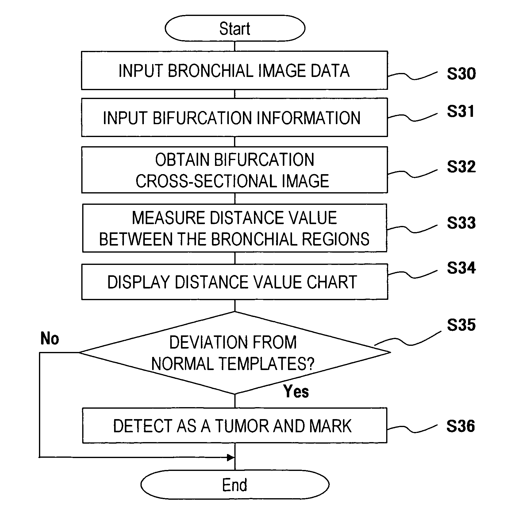
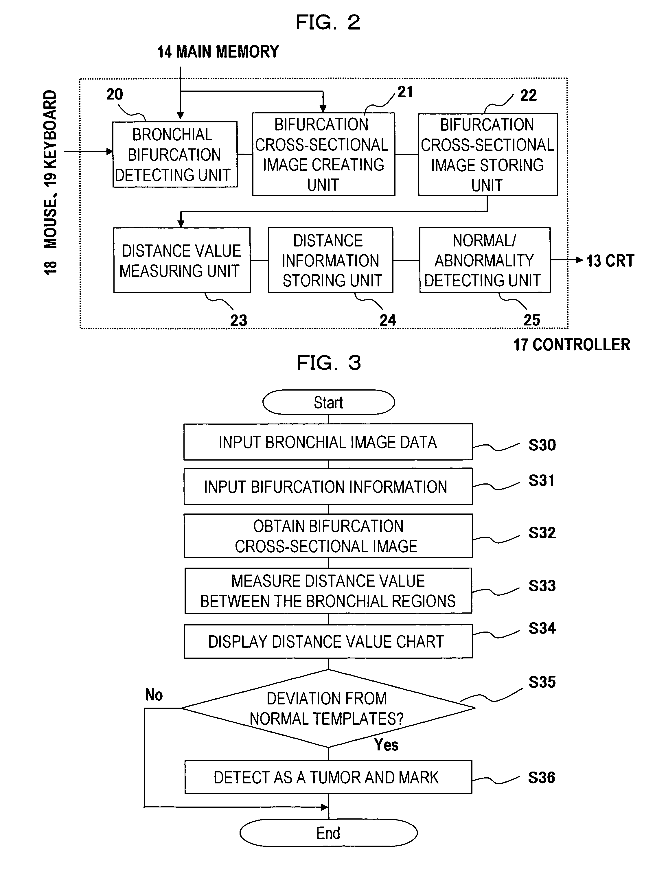
[0116]FIG. 3 is a flow chart explaining the operation example of the first embodiment, and FIGS. 4 to 8 are the explanatory diagrams of steps S31˜S36 in FIG. 3.

[0117](Step S30)

[0118]An examiner (an operator) operates mouse 18 or other input device, and inputs to controller 17 the medical image data being read out from main memory 14.

[0119](Step S31)

[0120]The examiner (the operator) operates mouse 18, and inputs to controller 17 the bronchi bifurcation information from main memory 14 or other memory device. The bifurcation information here indicates the coordinate of the bifurcation and the direction vector of the bifurcation. The direction vector of the bifurcation indicates the vector that points to the direction of the bronchi right before the bifurcation as arrow 41 in FIG. 4.

[0121](Step S32)

[0122]Controller 17 creates the several pieces of the cross-sectional images that are orthogonal to the direction vector of the bifurcation as seen in a group of cross-sec...

second embodiment

The Second Embodiment

[0135]FIG. 9 is a flow chart explaining an operation example of the second embodiment, FIG. 10 is an explanatory diagram of step S92 in FIG. 9, FIGS. 11 and 12 are the explanatory diagrams of step S93 in FIG. 9, and FIG. 13 an explanatory diagram of step S95 in FIG. 9.

[0136](Step S90)

[0137]An operator operates mouse 18 or other input device, and inputs the medical image data being read out from main memory 14 or other memory device to controller 17.

[0138](Step S91)

[0139]The operator operates mouse 18, and inputs the information on bronchi bifurcation from main memory 14 to controller 17. The information on the bronchi bifurcation here means coordinates of the bifurcation and the vector direction of the bifurcation.

[0140](Step S92)

[0141]Controller 17 creates cross-sectional image 101 including vector direction 100 of the bifurcation as seen in FIG. 10, based on the inputted medical image data and the information of the bronchi bifurcation.

[0142](Step S93)

[0143]Co...

third embodiment

The Third Embodiment

[0152]FIG. 15 is a block diagram illustrating a detailed example of a controller in FIG. 1 for explaining the third and fourth embodiments.

[0153]Controller 17, as illustrated in FIG. 15, includes:

[0154]hollow viscera extracting unit 150 being electrically connected to mouse 18, keyboard 19 and main memory 14;

[0155]notable region setting unit 151 being electrically connected to mouse 18, keyboard 19 and hollow viscera extracting unit 150;

[0156]hollow viscera cross-sectional image creating unit 152 being electrically connected to notable region setting unit 151;

[0157]lesion candidate detecting unit 153 being electrically connected to hollow viscera cross-sectional image creating unit 152; and

[0158]lesion candidate detecting result storing unit 154 being electrically connected to lesion candidate detecting unit 153.

[0159]Hollow viscera extracting unit 150 is for extracting the notable hollow viscera from the medical image being inputted from modality 1B via main mem...


PUM


Abstract

A medical image diagnosis support device comprises an organ region setting means, a deformation degree calculating means for calculating the deformation degree of the organ region set by the organ region setting means, a reference value storing means, a lesion detecting means for comparing the stored reference value with the deformation degree calculated by the deformation calculating means and for detecting existence of a lesion of the organ region from the comparison result, and a presenting means for presenting the existence to the examiner at least either visually or auditorily. Thus, the device can make a diagnosis selectively only on an organ region deformed because of a lesion and present it to the examiner visually such as by means of an image display or auditorily such as by means of speech, thereby improving the efficiency of diagnosis.

Description

TECHNICAL FIELD[0001]The present invention relates to a medical image diagnosis support device for supporting image diagnosis using a medical image obtained from a medical image diagnostic apparatus (including MRI apparatus, X-ray CT apparatus, and ultrasonic diagnostic apparatus), and in particular to a medical image diagnosis support device for supporting a diagnosis for organ regions with different figurations according to the symptom of a subject.BACKGROUND OF THE INVENTION[0002]The examination of a tumor for a subject has been executed by obtaining images with endoscopes being intubated into the hollow viscera regions such as trachea, respiratory system, and intestinal canal.[0003]However, the above examinations have been imposing a strain on the subjects such as the pain of intubating the endoscopes into the hollow viscera regions of the subjects.[0004]Virtual endoscopy described in Patent Document 1 cut down the burden on the subject because it uses data of X-ray CT images th...

Claims


Application Information

Patent Timeline
Patent Type & Authority Patents(United States)
IPC IPC(8): G06K9/00G06K9/46G06K9/48G06K9/66A61B6/00
CPCA61B6/00A61B6/466A61B6/463
Inventor SHIRAHATA, TAKASHIGOTO, YOSHIHIRONAKAGAWA, TORU
Owner FUJIFILM HEALTHCARE CORP
Why Eureka
Try Eureka