X-ray computed tomography apparatus and image processing apparatus

a computed tomography and computed tomography technology, applied in the field of x-ray computed tomography apparatus and image processing apparatus, can solve the problems of large amount of data to be processed, image does not contain any information, and arises in terms of processing time, so as to improve the efficiency of diagnosis

Inactive Publication Date: 2009-01-29
TOSHIBA MEDICAL SYST CORP
View PDF4 Cites 35 Cited by
  • Summary
  • Abstract
  • Description
  • Claims
  • Application Information

AI Technical Summary

Benefits of technology

[0008]It is an object of the present invention to provide an X-ray computed tomography apparatus and image processing apparatus which can improve the efficiency of diagnosis based on a plurality of volume data sets.

Problems solved by technology

In addition, when blood vessel image data is generated on the basis of the volume data set, of all the volume data sets, which concern a predetermined period of time, the generated blood vessel image does not contain any information about a blood vessel at which a contrast agent has not arrived within the predetermined period of time.
When function analysis based on TDC (e.g., an algorithm such as the deconvolution method) is to be executed on the basis of a plurality of volume data sets with different scan times, since the amount of data to be processed is large, a problem arises in terms of processing time.

Method used


Image

  • X-ray computed tomography apparatus and image processing apparatus
  • X-ray computed tomography apparatus and image processing apparatus
  • X-ray computed tomography apparatus and image processing apparatus

Examples


first embodiment

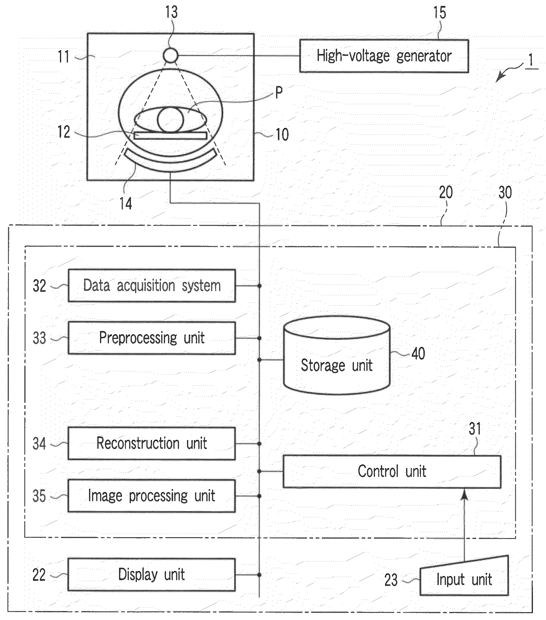
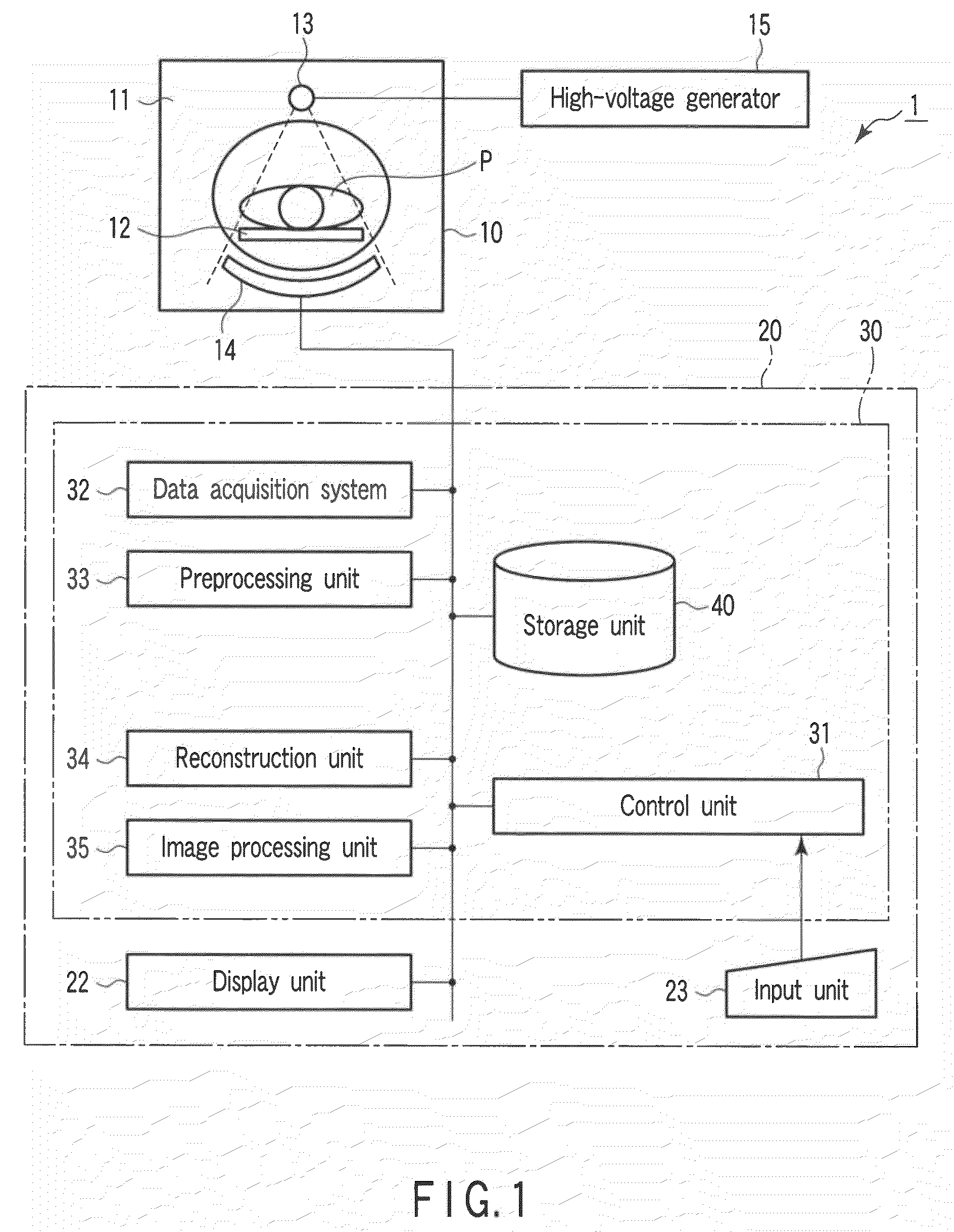
[0029]FIG. 1 is a block diagram showing the arrangement of an X-ray computed tomography apparatus (referred to as an X-ray CT apparatus hereinafter) 1 according to the first embodiment. The X-ray CT apparatus 1 includes a gantry 10 and a computer apparatus 20. The gantry 10 rotatably supports an annular or disk-like rotating frame 11. The rotating frame 11 has an X-ray tube 13 and an X-ray detector 14 which face each other through an object P placed on a top 12 in an imaging area. The rotating frame 11 continuously rotates the X-ray tube 13 and the X-ray detector 14 at a predetermined angular velocity. The X-ray tube 13 generates X-rays upon receiving a high voltage and filament current from a high-voltage generator 15. Typically, the X-ray tube 13 generates cone beam X-rays having a large cone angle and generally having a quadrangular pyramidical shape. A data acquisition system (DAS) 32 is connected to the X-ray detector 14. The X-ray detector 14 has a plurality of detection eleme...

second embodiment

[0070]FIG. 9 is a block diagram showing the arrangement of an X-ray CT apparatus 50 according to the second embodiment of the present invention. Note that the same reference numbers denote constituent elements having substantially the same functions as in the first embodiment, and a repetitive description will be made only when required.

[0071]As shown in FIG. 9, the X-ray CT apparatus 50 includes a gantry 10 and a computer apparatus 70. The computer apparatus 70 comprises an image processing apparatus 80, a display unit 22, and an input unit 23. The image processing apparatus 80 includes a control unit 31 as a main unit, a data acquisition system 32, a preprocessing unit 33, a reconstruction unit 34, a projection data processing unit 36, and a storage unit 40.

[0072]The data acquisition system 32 amplifies the current signal read out from each detection element of an X-ray detector 14 and converts the current signal into a digital signal. The data output from the data acquisition sys...


PUM


Abstract

An X-ray tube generates X-rays. An X-ray detector detects X-rays generated from the X-ray tube and transmitted through an object to be examined. A rotating frame continuously rotates the X-ray tube and the X-ray detector around the object. A reconstruction unit reconstructs a plurality of first volume data sets with different scan times for the same scan area of the object on the basis of an output from the X-ray detector. An image processing unit generates single second volume data set corresponding to a maximum value, an average value, a median value, or minimum value of the plurality of reconstructed first volume data sets in the temporal direction.

Description

CROSS-REFERENCE TO RELATED APPLICATIONS[0001]This application is based upon and claims the benefit of priority from prior Japanese Patent Application No. 2007-192257, filed Jul. 24, 2007, the entire contents of which are incorporated herein by reference.BACKGROUND OF THE INVENTION[0002]1. Field of the Invention[0003]The present invention relates to an X-ray computed tomography apparatus and image processing apparatus which generate a plurality of volume data sets with different scan times for the same scan area of an object to be examined.[0004]2. Description of the Related Art[0005]In an X-ray computed tomography apparatus, a technique called a 4DCT scan is available to generate a plurality of volume data sets with different scan times for the same scan area. Recently, this 4DCT scan can superimpose a blood vessel image and a functional image for a blood flow (perfusion). This superimposition processing is useful for image diagnosis. A blood vessel image concerns a time (e.g., a ti...

Claims


Application Information

Patent Timeline
Patent Type & Authority Applications(United States)
IPC IPC(8): G06K9/00A61B6/00
CPCA61B6/032A61B6/481A61B6/507A61B6/5235Y10S378/901A61B6/504
Inventor TSUKAGOSHI, SHINSUKEFUJISAWA, YASUKO
Owner TOSHIBA MEDICAL SYST CORP
Why Eureka
Try Eureka