Industrial multilayer fabric having a narrowing weft
a multi-layer fabric and narrowing technology, applied in the field of industrial multi-layer fabrics, can solve the problems of reducing the strength of the joining portion which has been made endlessly, reducing the water retained by the wire, and deteriorating the rigidity of the fabric, so as to improve the rigidity, wear resistance, and dehydration the effect of property
- Summary
- Abstract
- Description
- Claims
- Application Information
AI Technical Summary
Benefits of technology
Problems solved by technology
Method used
Image
Examples
embodiment 1
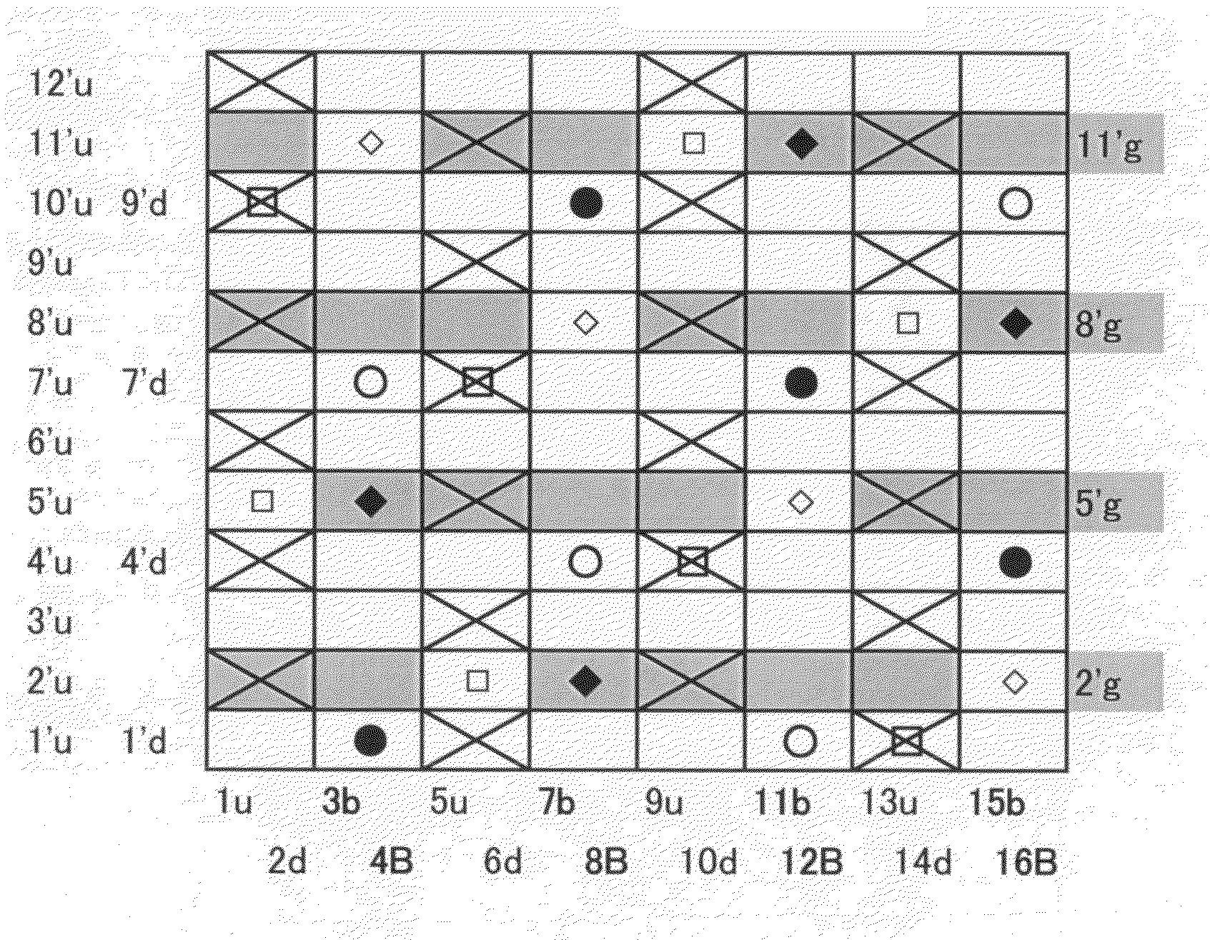
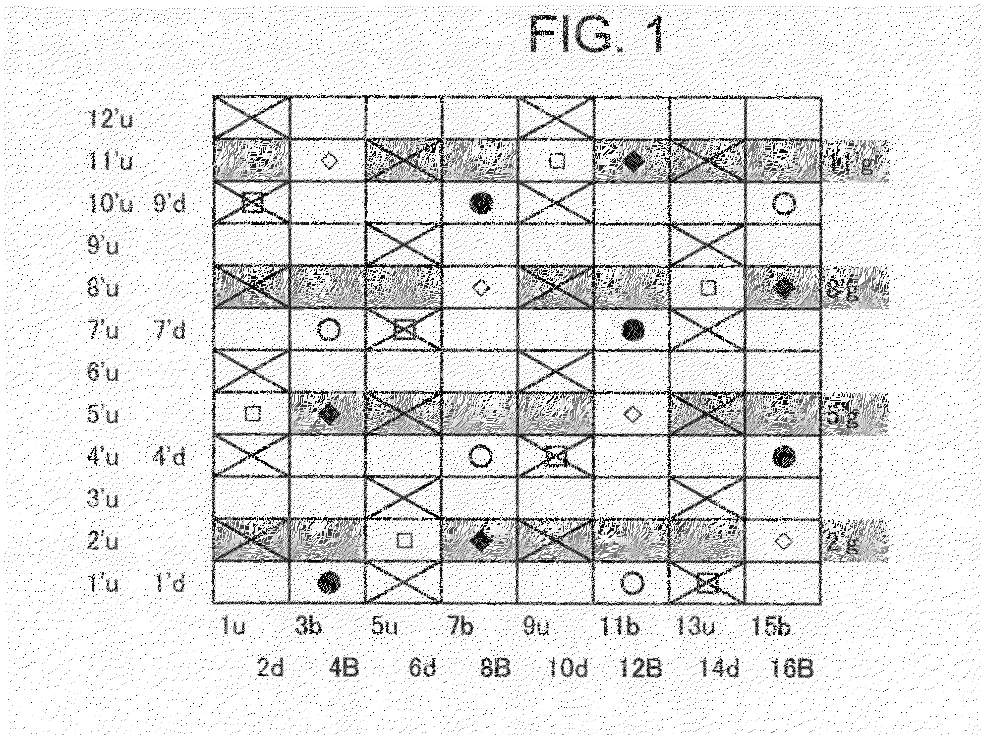
[0075]FIG. 1 is a design diagram of a double warp-double weft warp-binding structure according to Embodiment 1 of the present invention. In addition to upper side warps (u) and lower side warps (d), there are four pairs of a warp binding yarn (b) and a warp binding yarn (B). Narrower wefts are arranged alternately with lower side wefts and an arrangement ratio of upper side wefts to lower side wefts is 3:2.
[0076]As shown in the photograph of FIG. 13 illustrating the reverse side of the embodiment of the present invention, narrower wefts are placed between lower side wefts. The narrower wefts have a smaller diameter than lower side wefts and form a shorter crimp than that of lower side wefts on the lower side surface. According to this embodiment, lower side wefts each has a design in which it passes over two warps and then under six warps. narrower wefts each has a design in which it passes over one warp, under two warps, over one warp, and under four warps.
[0077]Narrower wefts form...
embodiment 2
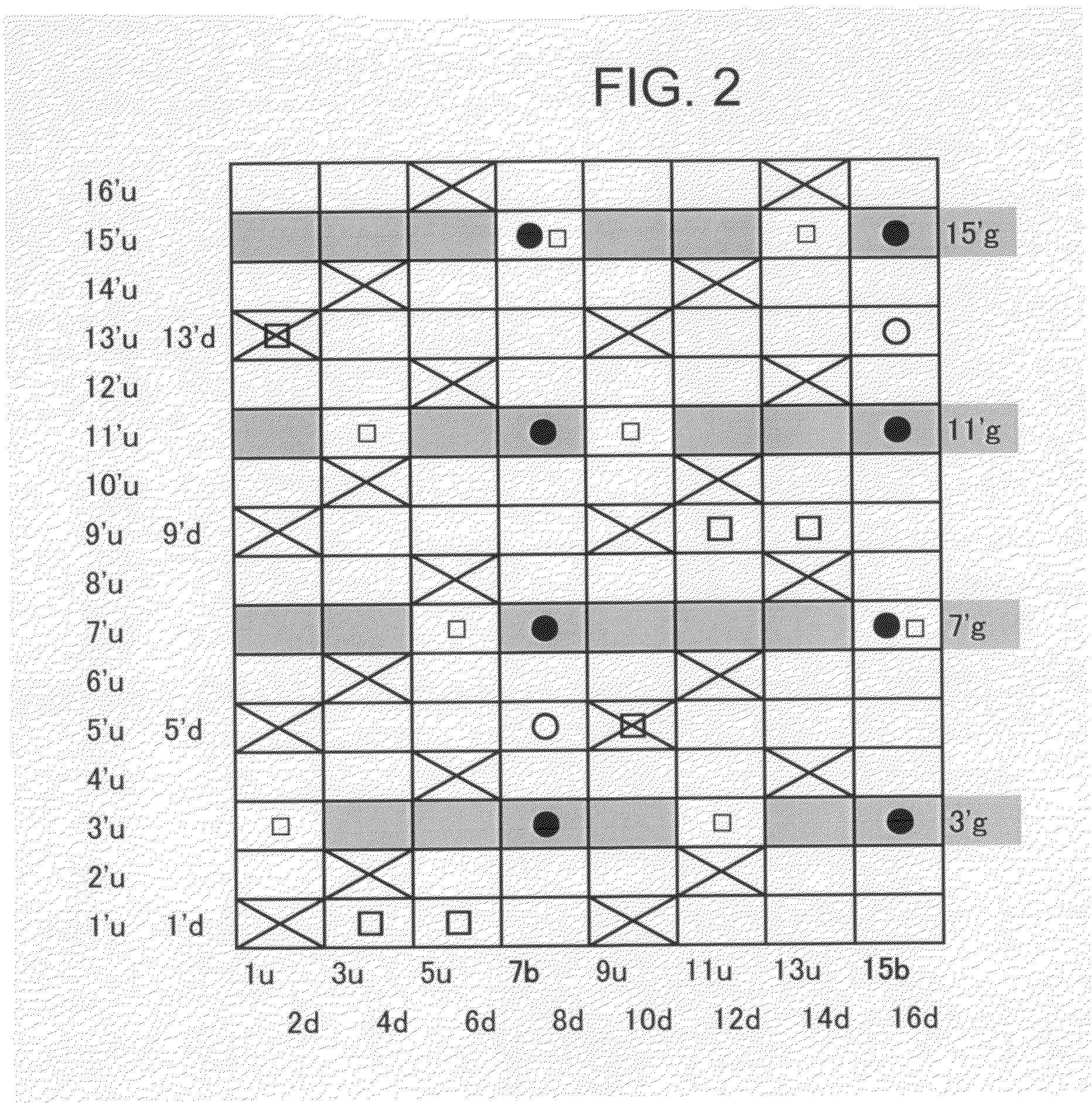
[0081]FIG. 2 is a design diagram of a fabric according to Embodiment 2 of the present invention. It is similar to the fabric of the above Embodiment and has a double warp-double weft warp-binding structure, but different in that a pair of warp binding yarns is composed of a warp binding yarn (b) and a lower side warp (d) and in an arrangement ratio, surface design, and an upper weft / lower weft ratio of 2:1. In Embodiment 1, a warp binding yarn is not involved in the formation of a surface design, while in the present embodiment, a warp binding yarn has both a function of a binding yarn and a function of an upper side warp. Upper side warps and warp binding yarns are woven with upper side wefts to form a sateen weave design.
[0082]Narrower wefts form, at a knuckle portion “∘” formed by a lower side warp passing under a lower side weft, crimps on the lower side surface (shaded portions) so as to sandwich the knuckle from both sides. This enables to form a fabric having improved rigidit...
embodiment 3
[0083]FIG. 3 is a design diagram of a fabric according to Embodiment 3 of the present invention. It is different from Embodiment 1 in the arrangement of warp binding yarns. The fabric of this embodiment has a pair of two warp binding yarns (b, B) and a pair of an upper side warp (u) and a warp binding yarn (B). Lower side wefts each passes over one warp (“∘” or “□”) to form a knuckle portion and then passes under seven warps to form a long crimp. Narrower wefts each repeats a design in which it passes over one warp and then passes under three warps to form a crimp which is shorter than that of the lower side wefts to sandwich the knuckle portion.
PUM
| Property | Measurement | Unit |
|---|---|---|
| diameter | aaaaa | aaaaa |
| diameter | aaaaa | aaaaa |
| diameter | aaaaa | aaaaa |
Abstract
Description
Claims
Application Information
 - R&D
- Intellectual Property
- Life Sciences
- Materials
- Tech Scout
- Unparalleled Data Quality
- Higher Quality Content
- 60% Fewer Hallucinations
Browse by: Latest US Patents, China's latest patents, Technical Efficacy Thesaurus, Application Domain, Technology Topic, Popular Technical Reports.
© 2025 PatSnap. All rights reserved.Legal|Privacy policy|Modern Slavery Act Transparency Statement|Sitemap|About US| Contact US: help@patsnap.com


