
Tire tread with directional design

a technology of directional design and tread, which is applied in the direction of non-skid devices, vehicle components, transportation and packaging, etc., can solve the problems of reducing the width of the groove, reducing the ability to drain water away from the contact patch, and the overall rigidity of the tread, so as to reduce the width and mechanical strength of the tread overall. , the effect of high mechanical stress

Active Publication Date: 2015-10-22
MICHELIN & CO CIE GEN DES ESTAB MICHELIN
View PDF9 Cites 0 Cited by
  • Summary
  • Abstract
  • Description
  • Claims
  • Application Information

AI Technical Summary

Benefits of technology

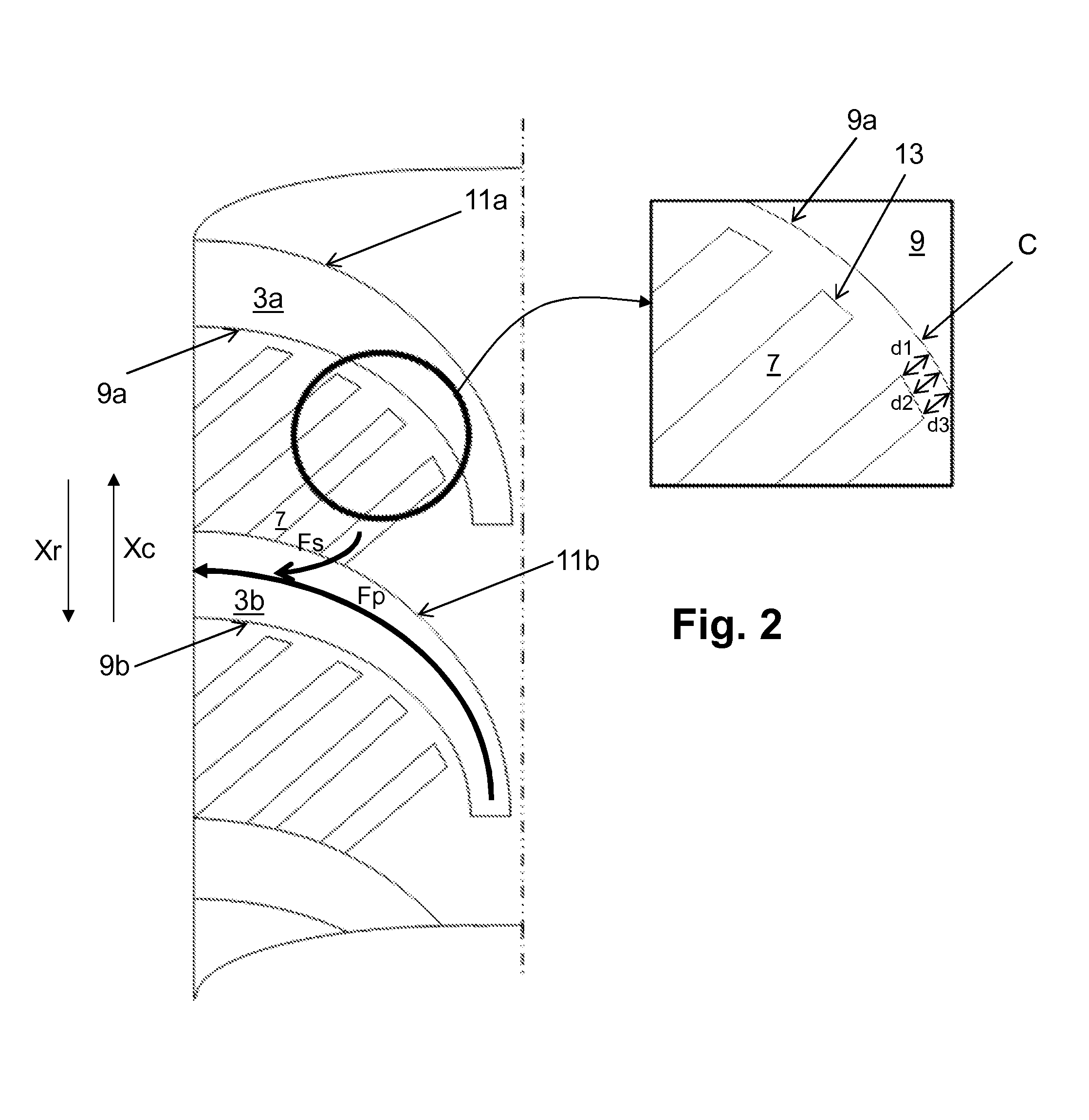
The invention improves the ability of tires to remove water from their contact patch by designing cavities that have optimal flow paths for water removal. By keeping the cavities open to the inside of the grooves, the tire can better manage the flow of water and prevent disruption from vortices. Additionally, optimizing the length and width of the cavity exits helps improve the tire's ability to bite into a snowy road surface. Finally, creating an intermediate part with reduced width improves the tire's mechanical strength while driving.

Problems solved by technology

With tread wear, the heights of the grooves decrease and this decreases their ability to drain water away from the contact patch.
Furthermore, with this wear, the tread becomes more rigid overall.

Method used


Image

  • Tire tread with directional design
  • Tire tread with directional design
  • Tire tread with directional design

Examples


Embodiment Construction

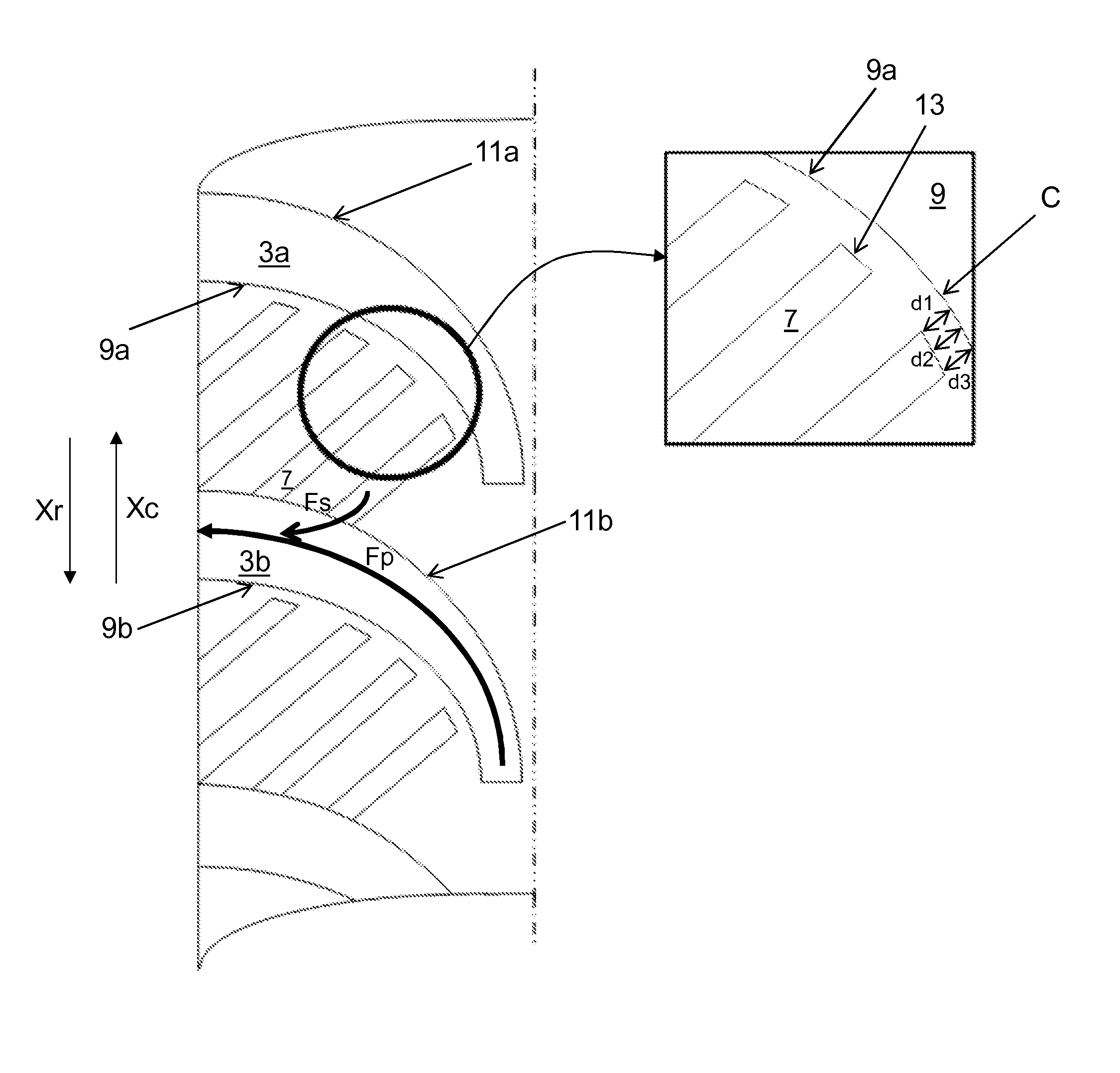
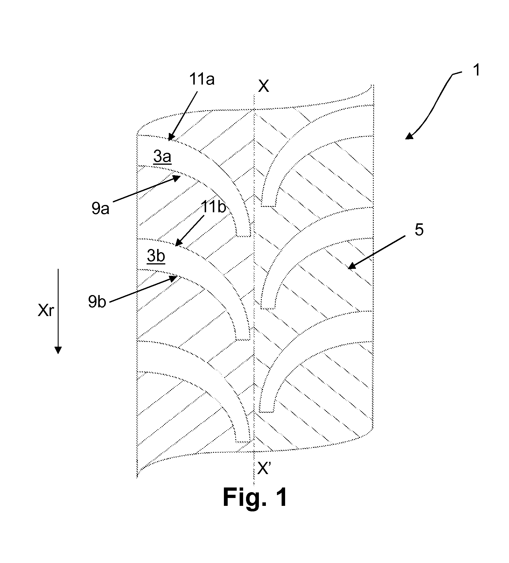
[0037]FIG. 1 schematically depicts a tread surface of a tread 1 in the new state. It is this tread surface that will come into contact with a road surface when a tire which comprises this tread is being driven on.

[0038]In more detail, the tread 1 comprises a plurality of grooves 3a, 3b formed on each half of the tread on either side of a midplane X-X′. Each of these grooves opens axially to the outside, namely towards the shoulder parts of the tire (which have not been depicted here) and extend axially towards the midplane X-X′ with a predetermined curvature. These grooves 3a, 3b form on the tread a first pattern in the overall shape of a V pointing in a groove direction Xr. More specifically, each groove delimits a first wall of material 9a, 9b on the inside of the curvature of the groove and a second wall of material 11a, 11b opposite the first wall of material. The tread further comprises a plurality of sipes 5. Each of these sipes extends here between two adjacent grooves in an ...


PUM


Abstract

A tread having a plurality of grooves formed on each half of the tread on each side of a midplane X-X′, each opening axially to the outside and extending axially towards the midplane X-X′ so that the plurality of grooves forms a first pattern in the overall shape of a V pointing in a groove direction Xr. The tread includes a plurality of sipes. From a certain degree of wear onwards, all or some of the sipes become enlarged forming cavities extending in an oblique direction forming a second pattern in the overall shape of a V pointing in a cavity direction Xc. Each of these cavities opens into just one of the grooves of the tread, the plurality of grooves forming, at this level of wear, the same first pattern.

Description

[0001]This application is a 371 national phase entry of PCT / EP2013 / 074431, filed 22 Nov. 2013, which claims benefit of French Patent Application No. 1261418, filed 29 Nov. 2012, the entire contents of which are incorporated herein by reference for all purposes.BACKGROUND[0002]1. Field[0003]The present disclosure relates to a tread for a tire intended to be fitted to a passenger vehicle. More particularly, the disclosure relates to a tire that has improved performance for winter driving or driving in the wet.[0004]2. Description of Related Art[0005]Document U.S. Pat. No. 4,057,089 discloses a tread comprising a directional pattern. The “pattern” of a tread means a plurality of cuts made in this tread to a predetermined design, these cuts having a suitable width and depth. A cut generically refers either to a groove or to a sipe and corresponds to the space delimited by the walls of material facing one another and distant from one another by a non-zero distance. What differentiates a ...

Claims


Application Information

Patent Timeline
IPC IPC(8): B60C11/12B60C11/13
CPCB60C11/13B60C11/1204B60C11/0302B60C2011/1209B60C11/1281B60C11/0323B60C2011/0374B60C11/12B60C2011/0381B60C11/03
Inventor LEDIEU, VINCENTFRAENKEL, BERTRANDBATNINI, ILLYESVANTAL, MARIE-HELENE
Owner MICHELIN & CO CIE GEN DES ESTAB MICHELIN
Learn More