
Ratchet one-way clutch with vibration dampening

a one-way clutch and vibration damping technology, which is applied in the direction of fluid gearings, couplings, belts/chains/gearings, etc., can solve the problems of generating undesirable noise and vibration, unable or even impossible to incorporate the counteracting components noted above using stamped components, and generating noise and vibration. the effect of minimal vibration and nois

Inactive Publication Date: 2011-03-01
SCHAEFFLER TECH AG & CO KG
View PDF20 Cites 4 Cited by
  • Summary
  • Abstract
  • Description
  • Claims
  • Application Information

AI Technical Summary

Benefits of technology

[0011]It is a general object of the present invention to provide a one-way clutch in a stator that produces minimal vibration and noise when shifting to a locked mode.
[0012]It is another object of the present invention to provide a one-way clutch in a stator with dampening between components used to transfer torque during a locked mode.
[0013]It is a further object of the present invention to use stamped parts in a stator and a one-way clutch to provide an assembly that produces minimal vibration and noise when the stator changes to a locked mode.

Problems solved by technology

The impact associated with the contact can generate undesirable noise and vibration.
Unfortunately, this degree of precision can be much greater than or even incompatible with the precision associated with the remaining components in the clutch.
However, it may be difficult or even impossible to incorporate the counteracting components noted above using stamped components.

Method used


Image

  • Ratchet one-way clutch with vibration dampening
  • Ratchet one-way clutch with vibration dampening
  • Ratchet one-way clutch with vibration dampening

Examples


Embodiment Construction

[0028]At the outset, it should be appreciated that like drawing numbers on different drawing views identify identical, or functionally similar, structural elements of the invention. While the present invention is described with respect to what is presently considered to be the preferred aspects, it is to be understood that the invention as claimed is not limited to the disclosed aspects.

[0029]Furthermore, it is understood that this invention is not limited to the particular methodology, materials and modifications described and as such may, of course, vary. It is also understood that the terminology used herein is for the purpose of describing particular aspects only, and is not intended to limit the scope of the present invention, which is limited only by the appended claims.

[0030]Unless defined otherwise, all technical and scientific terms used herein have the same meaning as commonly understood to one of ordinary skill in the art to which this invention belongs. Although any meth...


PUM


Abstract

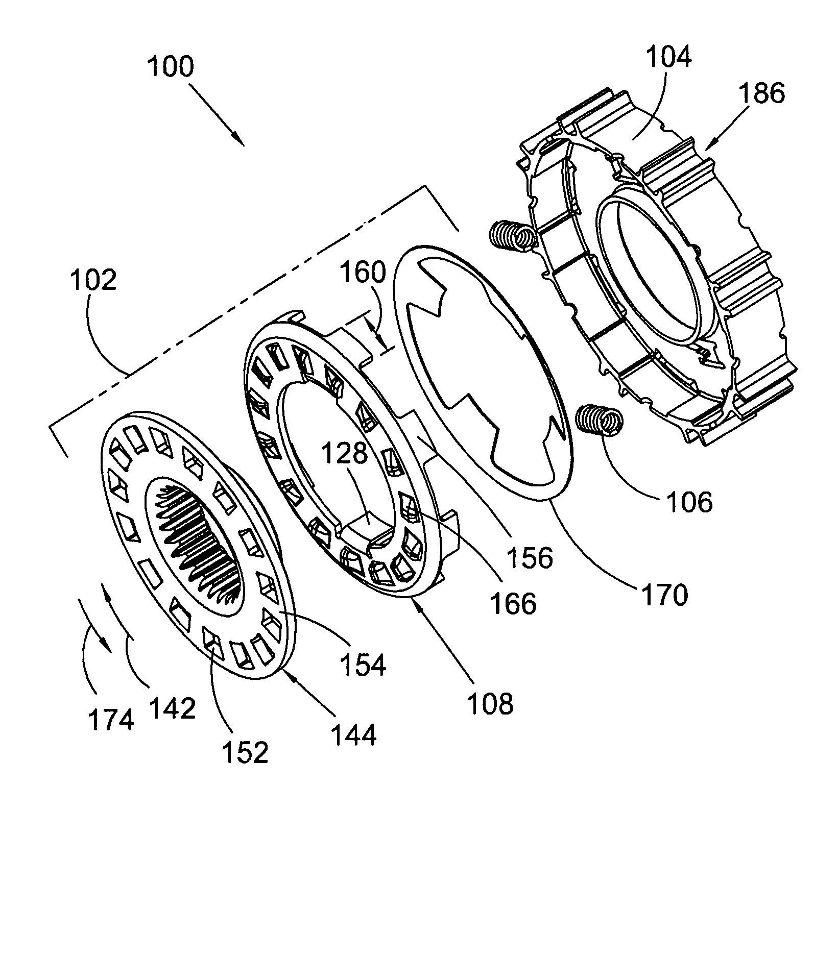
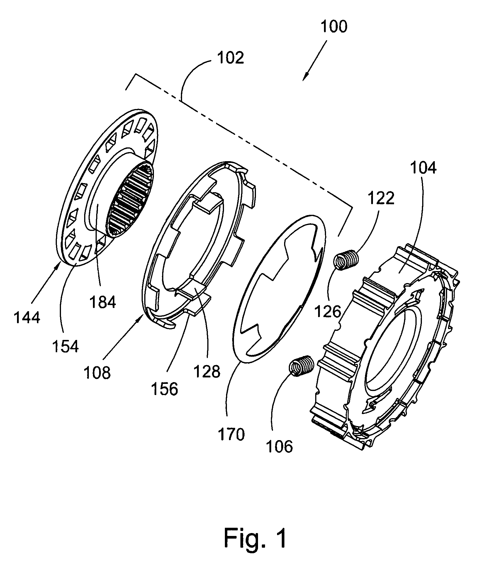
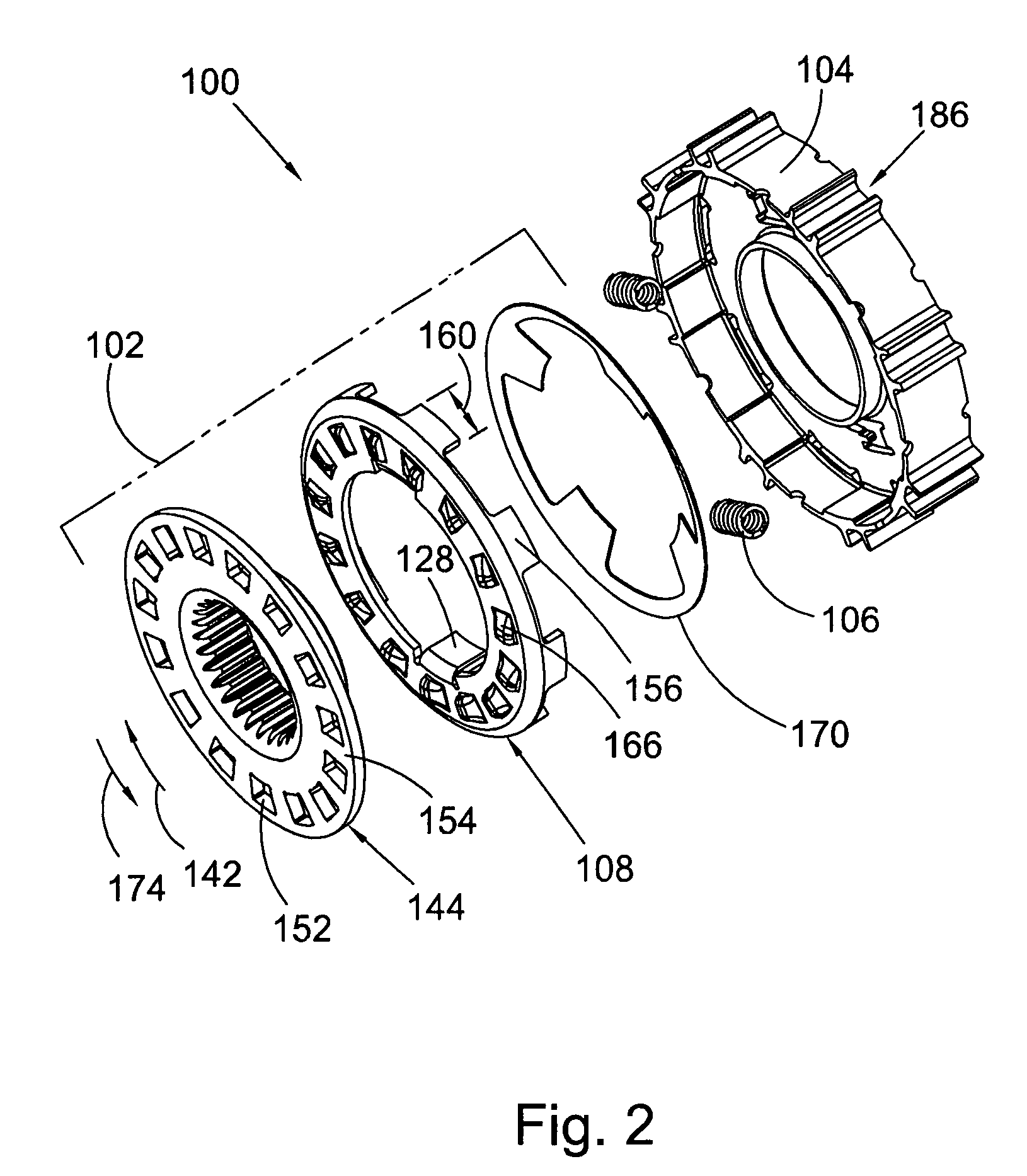
The present invention broadly comprises a stator and one-way clutch assembly including a segment of a stator, a one-way clutch engaged with the segment, and at least one elastically deformable element engaged with the segment and the clutch and arranged to dampen transfer of torque from the stator to the clutch. In some aspects, the clutch includes a first plate and the deformable element is engaged with the segment and the plate. The segment urges the deformable element against the first plate. The first plate is arranged to rotate in response to the urging. The segment and the first plate are arranged to rotationally lock. The first plate and a second plate, connected to a clutch hub, rotationally lock in response to the urging, and the segment and the first plate are arranged to rotationally lock following the locking of the first and second plates.

Description

CROSS-REFERENCE TO RELATED APPLICATIONS[0001]This application claims the benefit under 35 U.S.C. §119(e) of U.S. Provisional Application No. 60 / 785,684 filed Mar. 24, 2006.FIELD OF THE INVENTION[0002]The invention relates to improvements in apparatus for transmitting force between a rotary driving unit (such as the engine of a motor vehicle) and a rotary driven unit (such as the variable-speed transmission in the motor vehicle). In particular, the invention relates to a stator and one-way clutch assembly, with vibration dampening, in a stator. The assembly provides a dampening means between the stator and the clutch to minimize impact, noise, and vibration associated with the transition from free-wheel mode to locked mode in the stator.BACKGROUND OF THE INVENTION[0003]One-way clutches are used in stators to rotationally disengage the blades of the stator from the shaft of the stator during a free-wheel mode and to rotationally lock the blades and the stator shaft during a locked mod...

Claims


Application Information

Patent Timeline
Patent Type & Authority Patents(United States)
IPC IPC(8): F16D41/18F16D33/00
CPCF16D3/66F16D41/125F16D47/02F16H41/24F16H2041/246
Inventor BREES, WILLIAM
Owner SCHAEFFLER TECH AG & CO KG
Learn More