Dimmable ballast for an electrodeless discharge lamp

a technology of electrodeless discharge and ballast, which is applied in the direction of electric variable regulation, process and machine control, instruments, etc., can solve the problem of not completely satisfying the ballast, and achieve the effect of minimising nois

Inactive Publication Date: 2008-03-04
MATSUSHITA ELECTRIC WORKS LTD
View PDF10 Cites 14 Cited by
  • Summary
  • Abstract
  • Description
  • Claims
  • Application Information

AI Technical Summary

Benefits of technology

[0006]In view of the above insufficiency the present invention has been accomplished to provide an improved ballast for an electrodeless discharge lamp. The ballast in accordance with the present invention includes an induction coil adapted in use to be disposed adjacent the discharge lamp, and a high frequency power supply that supplies a high frequency electric power to the induction coil for operating the lamp. A dimmer controller is included to generate a control signal in response to a dimmer command designating a varying dimming ratio. The control signal defines a first period in which the power supply is controlled to apply a coil voltage of a first level to the induction coil for operating the lamp. The first period is followed by a second period in which the power supply is controlled to apply the coil voltage of a second level that is lower than the first level and fails to sustain the lamp. The control signal generated from the dimmer controller is characterized to define, between the second period and the first period, a starting period in which the coil voltage increases continuously. Thus, the lamp can be started only at a minimum noise so as to be smoothly changed from the off-condition to the on-condition, thereby assuring a successful lamp dimming with the minimum noise.
[0008]Also, the control signal is preferred to define, in the end of the first period, a falling phase in which the coil voltage decreases continuously towards the second level. Whereby, the lamp can be smoothly changed from the on-condition to the off condition, reducing the noise also at this transition.
[0010]Preferably, the control signal is defined to decrease the duty ratio of the first period as the dimming ratio decreases to lower the luminance of the lamp to a predetermined level, and to decrease the coil voltage of the first period and the duty ratio as the dimming ratio decreases to lower the luminance further beyond the predetermined level. With this arrangement, it is easy to dim the lamp to a deep extent, i.e., over a wide dimming range from the full luminance to a minimum luminance of the lamp.
[0011]Further, the control signal may be configured to increase the coil voltage of the second period as the dimming ratio decreases. Thus, the lamp can keep residual plasma at a relatively high level even in the second period, i.e., in the off-condition, such that the lamp can be successfully started by being applied the coil voltage of the first level in the immediately subsequent first period. Therefore, the lamp can be successfully dimmed to a deep extent.
[0013]Further, the control signal may be configured to increase the coil voltage at the beginning of the starting period as the dimming ratio increases. Thus, the lamp can be started rapidly as the dimming ratio increases, which makes it possible to vary the duty ratio of the first period to a large extent and accordingly to assure the lamp dimming over a wide range.

Problems solved by technology

Although the above control scheme is found successful for dimming the lamp, there remains a problem in that the ballast sees an abrupt increase of the coil voltage at the very beginning of the first period, which would cause undesired noises, and therefore the prior ballast is not completely satisfactory.

Method used


Image

  • Dimmable ballast for an electrodeless discharge lamp
  • Dimmable ballast for an electrodeless discharge lamp
  • Dimmable ballast for an electrodeless discharge lamp

Examples


Embodiment Construction

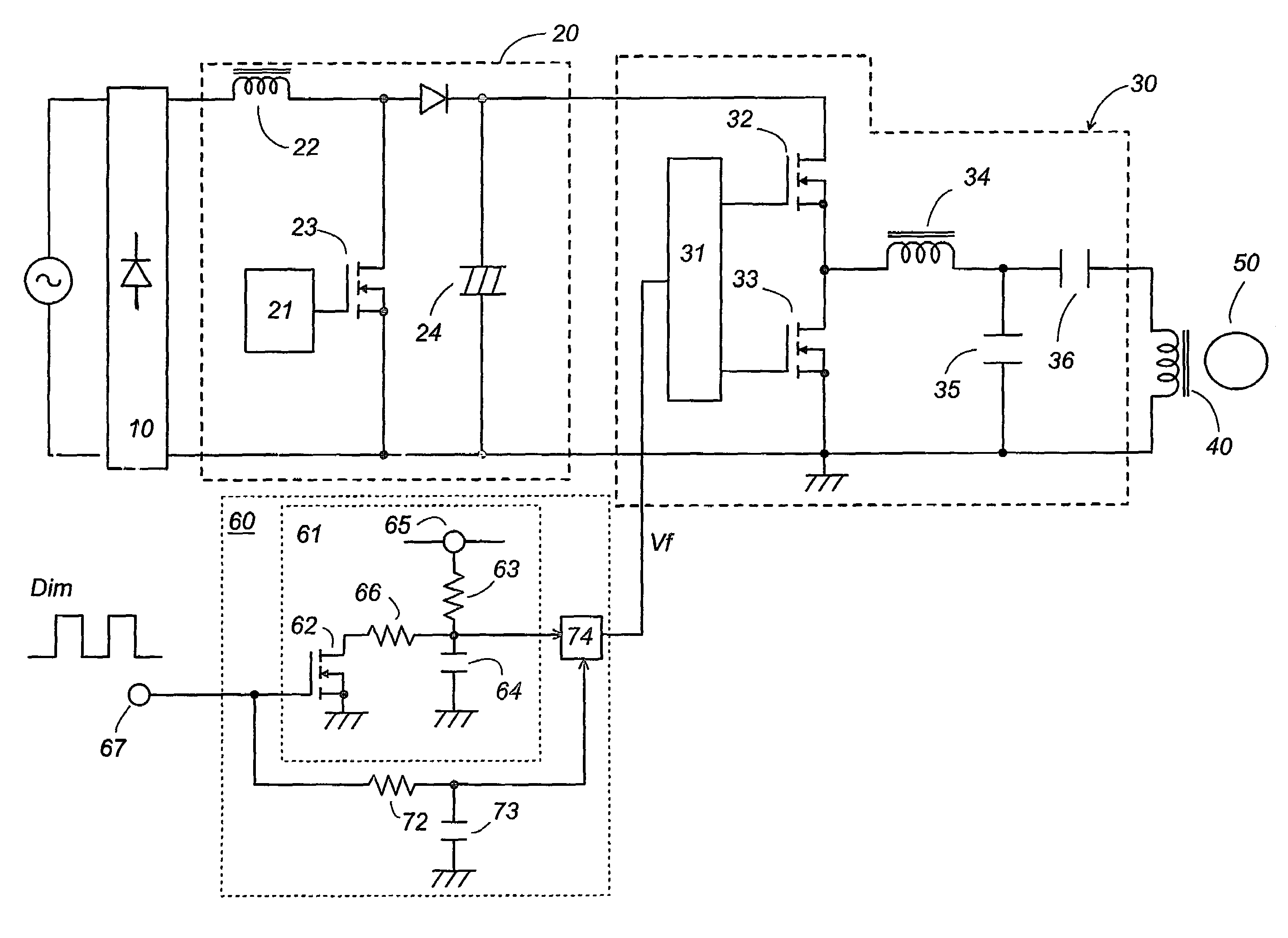
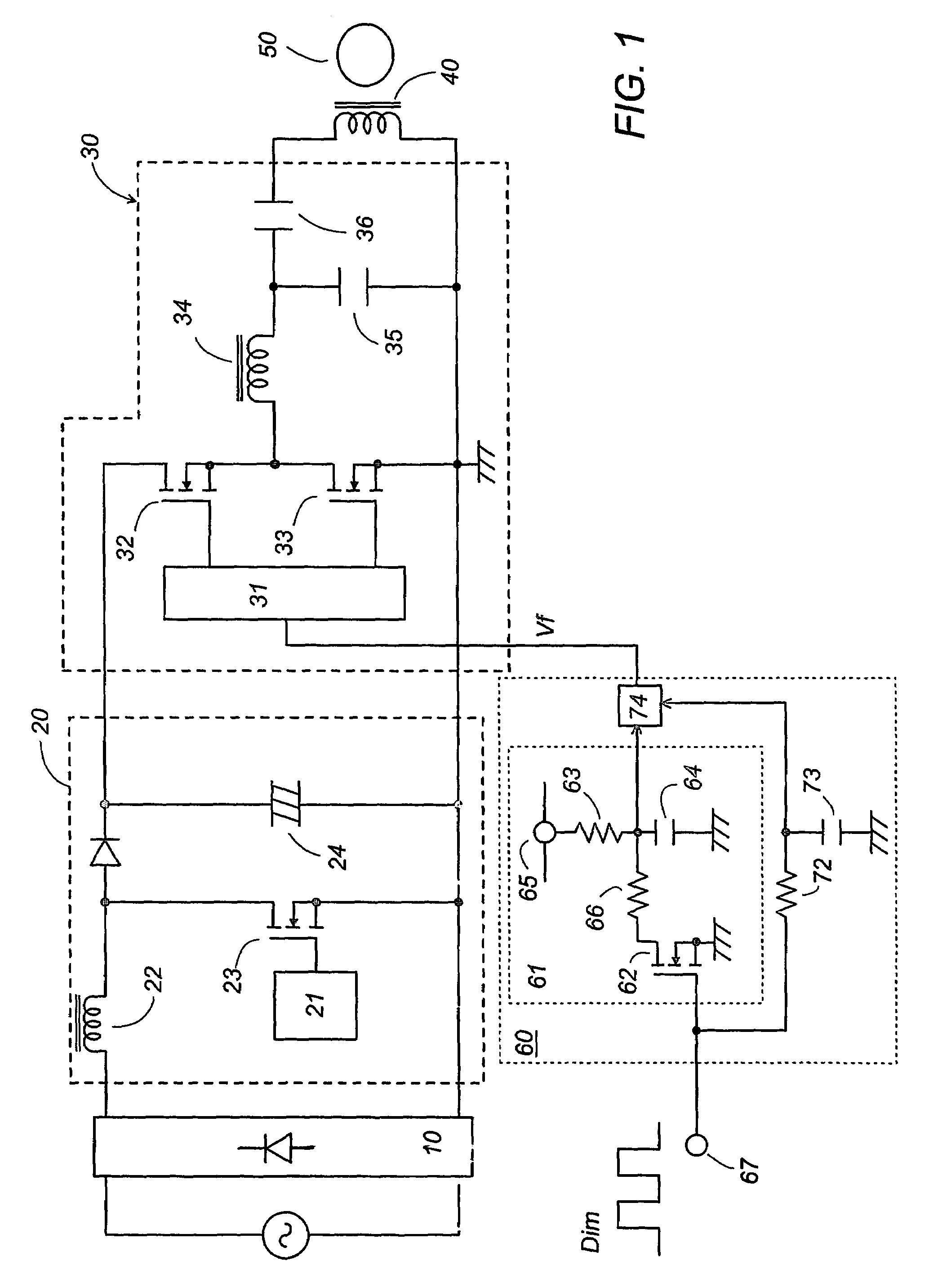
[0039]Referring now to FIG. 1, there is shown an electronic ballast for an electrodeless lamp in accordance with a preferred embodiment of the present invention. The ballast includes an induction coil 40 adapted in use to be disposed adjacent to the electrodeless discharge lamp 50 for supplying the electric power to the lamp. The ballast is designed for dimming the lamp, i.e., adjusting the luminance of the lamp, and includes a rectifier 10 providing a rectified DC voltage from an AC voltage source, a DC voltage regulator 20 providing a regulated DC voltage, and a high frequency power supply, i.e., an inverter 30 powered by the output of the DC voltage regulator 20 to supply a high frequency AC power to the discharge lamp 50. The inverter 30 includes a resonant circuit through which the high frequency AC power is supplied to the discharge lamp 50.

[0040]The DC voltage regulator 20 is in the form of a conventional chopper having an inductor 22 and a switching element 23 which is drive...


PUM


Abstract

A ballast for an electrodeless discharge lamp includes a high frequency power supply that supplies a high frequency electric power to an induction coil for operating the lamp. A dimmer controller generates a control signal in response to a dimmer command designating a varying dimming ratio. The control signal defines a first period Ton in which the power supply is controlled to apply a coil voltage of a first level V1 to the induction coil for operating the lamp. The first period is followed by a second period Toff in which the power supply is controlled to apply the coil voltage of a second level V2 that is lower than the first level and fails to sustain the lamp. The control signal defines, between the second period and the first period, a starting period Tst in which the coil voltage increases continuously for smooth transition from an off-condition to an on-condition of the lamp.

Description

[0001]This application is a 371 of PCT / JP03 / 14951 filed Nov. 21, 2003 which claims priority of JP 2003-036518 filed Feb. 14, 2003.[0002]1. Technical Field[0003]The present invention relates to a ballast for an electrodeless discharge lamp, and more particularly to the ballast having a lamp dimming capability.[0004]2. Background Art[0005]U.S. Pat. No. 6,175,198 discloses a prior art ballast for operating the electrodeless discharge lamp having a lamp dimming capability. The ballast includes an induction coil disposed adjacent to the lamp, and a high frequency power supply that supplies a high frequency electric power to the induction coil for operating the lamp. Also included in the ballast is a dimmer controller that controls the power supply to vary a coil voltage being applied to the induction coil for dimming the lamp, in response to a dimmer command designating a dimming ratio, i.e., the ratio of rated luminance to an actual luminance. In order to dim the lamp, the dimmer contro...

Claims


Application Information

Patent Timeline
Patent Type & Authority Patents(United States)
IPC IPC(8): H05B41/24H05B41/28H05B41/392
CPCH05B41/2806H05B41/3925H05B41/3927Y02B20/22Y10S315/04Y02B20/00
Inventor MAKIMURA, SHINJIKIDO, HIROSHIMASUMOTO, SHINGOKUMAGAI, YUJINAKAJO, AKIRA
Owner MATSUSHITA ELECTRIC WORKS LTD
Why Eureka
Try Eureka